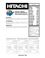
background image


Summary of Contents for C1422R

Page 1: ...sible 2 Amp time lag Leistungsaufnahme im standby mode 4W Netzspannung 220 240V 50Hz Sicherung 2 Amp time lag December 1998 No 0102 Model Chassis C1422R F1R C1422T F1Y C2122T F4Y CP1422R F1GR CP2122R F4GR CP1422T F1GY CP2022T F2GY CP2122T F4GY CP1422T 481 F1HY CP2122T 481 F4HY CP1422T 491 F1HY CP2022T 491 F2HY CP2122T 491 F4HY CS1422R F1KR CS2022R F2KR CS2122R F4KR CL1422R F1FR CL2122R F4FR SERVIC...

Page 2: ...2 ...

Page 3: ...te without danger of electrical shock The service technician must make sure that no protective device built into the instrument by the manufacturer has become defective or inadvertently damaged during servicing CE MARK 1 HITACHI products may contain the CE mark on the rating plate indicating that the product contains parts that have been specifically approved to provide electromagnetic compatibili...

Page 4: ...B rail isolation Consequently the mains isolation barrier is more convoluted than in a conventional chassis and a much larger portion of the chassis is non isolated Figure 1 shows the isolation barrier position in the chassis It can be seen that both the DST T401 and the scan coils now straddle the isolation barrier and are as such safety critical components Also the opto coupler I402 is required ...

Page 5: ...by active low outputs on pins 14 15 and 16 high mid low and transistors Q002 to Q004 The controller makes AFC corrections by reading on tune information from I501 via the I C bus As the tuner is controlled by voltage synthesis there is no direct correlation between the controller output and the tuned frequency Non volatile memory The non volatile memory I702 holds configuration information user se...

Page 6: ...ramme up or down The Normalize key selects factory picture settings immediately over writing user settings The digit keys 1 2 8 toggle the state of the individual bits 7 6 0 of the value of the current parameter for example pressing digit key 4 would change value 1F hex to 0F hex TO STORE THE CHANGES PRESS THE TV KEY ON THE HAND UNIT BEFORE REMOVING THE SERVICE MODE LINK THE MESSAGE STORED WILL BE...

Page 7: ...e 15 50 50 50 IF PLL adjustment Set to 50 hex 16 19 19 19 Vertical zoom Not used on this chassis 17 20 20 20 Vertical scroll Not used on this chassis 18 81 81 81 Control 2 Do not adjust 19 08 08 08 Control 3 Do not adjust 1A 00 00 00 Control 4 Do not adjust Service Parameter Functions Parameters above 1A are designated by two letter codes except text contrast on a teletext set These control config...

Page 8: ...01 If no text is present P100 will still appear in the top left corner of the screen together with some text on the bottom row of the display There is no on screen parameter adjust with volume control as normal and change parameter with programme up down keys AGC The AGC take over point should be adjusted via service parameter 13 such that the tuner output to the SAW filter is 600mV pk pk 300mV pe...

Page 9: ...each CRT gun to equalize the cut off points and therefore provide a true black For diagnostic purposes this control loop may be disabled by selecting service parameter 02 hue and pressing the number 2 key on the hand unit After repair the auto black level sampling should always be re enabled by pressing the number 2 key again and storing it with the TV key The value of parameter 02 toggles between...

Page 10: ...d to the load and C809 combination Start Up At start up the overwind output voltage T802 winding pins 7 8 is not present so a start up bias circuit is required This consists of R806 D802 and R809 Approximately 16V is produced at the junction of R806 and D802 which is fed via R809 to turn on Q801 for the first time Control Method During the on time of Q801 the buck inductor voltage flows through th...

Page 11: ... and waiting for line drive to start up would fail since the supply cannot deliver I501 s supply current In order to overcome this problem a system of pseudo line drive was devised which allows the line output stage to be driven by the µP in order to establish a B load prior to turn on of the video processor 8V supply Figure 6 is a block representation of this system The two line drive sources are...

Page 12: ...is not available at any point on the chassis it is read by the microcontroller via the I C bus Therefore one of the following methods can be used to correctly align the AFC a For demodulator tank coil fitted I501 TDA884X Mask 1 Tune a known channel Using a spectrum analyzer monitor pin 11 of H001 Fine tune the tuner for a carrier frequency of 38 9MHz Store the fine tuned frequency i e AFC off Ente...

Page 13: ...endent of the state of the other inputs to the OR circuit During mixed TV Text mode or whilst the OSD is showing on part of the screen this line will be switching at a high rate RGB mode can be selected manually by the user and in this case the open drain output on pin 8 of the micro controller will be switched off and will be pulled up to 1 7 volts by R307 and R306 Q302 then applies a voltage of ...

Page 14: ...tments required on the colour decoder On Screen Display The micro controller on screen display OSD supplies blanking and RGB signals for overlaying the television picture Pin 35 of I701 provides blanking pulses which are applied to pin 26 of I501 via Q301 to turn off the decoder RGB output so that the OSD is clearly visible The RGB signals from pins 34 33 and 32 of I701 are applied directly to the...

Page 15: ...When a line drive pulse is missed the line output transistor Q404 stays out of conduction because the LED of the opto coupler is forced into conduction by Q402 and R405 and R406 By this means damage is avoided when there is no line drive The line output transistor Q404 is helped in its switching action by the extra winding 2 3 while C412 helps in the switching action and prevents Q404 overheating ...

Page 16: ...input Should this pulse fail the picture tube outputs are blanked off until after about 12 seconds the micro controller records a failure For diagnostic purposes vertical protection during the 12 second interval may be disabled by pressing the 2 key on the remote control handunit when in service parameter OA This should always be re enabled after repair See adjustments section ...

Page 17: ...requency gain of each video amplifier is approximately 51 this being determined by the ratio of the feedback resistors to the input resistors The gain of each video amplifier channel above 2 2 MHz is increased by including a small capacitor across one of the two input resistors of each channel Video Amplifier Switch On Blanking The emitters of Q906 Q907 and Q908 are biased from the 200V video HT v...

Page 18: ...RGBIN I RGB insertion 27 LUMIN I Luminance 28 LUMOUT O Luminance 29 BYO O B Y signal 30 RYO O R Y signal 31 BYI I B Y signal 32 RYI I R Y signal 33 REFO O Sub carrier reference 34 XTAL1 3 58MHz crystal connection 35 XTAL2 4 43 3 58MHz crystal connection 36 DET Loop filter phase detector 37 VP2 2nd supply voltage 1 8V 38 CVBS1O O CVBS 1 39 DECDIG De coupling digital supply 40 HOUT O Horizontal 41 F...

Page 19: ...L GEOMETRY RGB CONTROL BLUE STRETCH OUTPUT BLACK STRETCH RGB MATRIX RGB 1 INPUT CD MATRIX SAT CONTROL SKIN TINT VIF AMPLIFIER PLL DEMOD CALIBRATION AFC VIDEO IDENT AVL SWITCH VOLUME LIMITER SOUND BANDPASS SOUND TRAP 48 49 IF IN 53 8 7 54 5 15 55 45 56 10 11 35 33 16 34 36 38 1 13 6 SD AA SCL H DRIVE TUNER TOP POL AFC SW REF HUE SW CVBS OUT C V B S I N MUTE IDENT AUDIO OUT 2 AUDIO IN VOL SW I C BUS...

Page 20: ...nsumption and allowing higher LED current The output on pin 21 of IC781 drives TR781 which provides high current pulses through infra red transmitter diode D781 Reservoir capacitor CE781 reduces momentary battery voltage drop which may otherwise affect the IC Infra red Receiver The chassis uses an integrated receiver IC702 which provides a fully demodulated output to the microcontroller through R7...

Page 21: ... key is detected or remote command received Tuning The tuning control voltage to the tuner is controlled via the PWM at pin 1 of I701 and integrating circuit around Q001 Minimum voltage is at maximum mark space ratio bottom of each band Band switching is controlled by active low outputs on pins 14 15 and 16 high mid low and transistors Q002 to Q004 The controller makes AFC corrections by reading o...

Page 22: ...mal numbers are displayed to the left of the screen the lefthand one is the service parameter number the righthand one is the value for that parameter Some parameters are identified by a two letter code instead of a number see below For example 0A 1F shows parameter ten 0A hex at thirty one 1F hex In this mode of operation some of the remote control keys have different functions The up and down an...

Page 23: ...justments section 0E 29 38 3D White point Blue 0F 1C 1C 1C Peaking sharpness Use picture menu control instead 10 5C 5C 5C Brightness Use picture menu control instead 11 9C 9C 9C Saturation Use picture menu control instead 12 1C 1C 1C Contrast Use picture menu control instead 13 13 13 13 AGC take over point See adjustments section 14 0A 0A 0A Volume 15 50 50 50 IF PLL adjustment Set to 50 hex 16 19...

Page 24: ... Analogue ground 23 CVBS0 I Composite video 24 CVBS1 25 Black I Video black level storage 26 Iref I Reference current 27 Frame 28 Test Ground 29 COR 30 P3 4 TDA884X Line drive gating high in standby start up low in operation 31 RGBref I RGB reference 32 OSD B O Blue OSD 33 OSD G O Green OSD 34 OSD R O Red OSD 35 OSD EN O OSD enable 36 H sync I Horizontal sync 37 V sync I Vertical sync 38 Vdda 5V d...

Page 25: ...the shaded area CVBS0 CVBS1 Reset I C PWM ADC Timer Ctrs Port 1 Port 2 Port 3 Port 0 data addr int Osc VSync HSync Frame XtalIn XtalOut OscGnd Black IRef P1 0 1 7 P3 0 3 4 P0 0 0 7 P2 0 2 7 Teletext Acquisition Acquisition Timing R G B VDS COR Data Slicer Display Page RAM Display Timing 16k x 8 ROM 256 x 8 RAM Text Interface 8051 CPU Fig 8 Block Diagram ...

Page 26: ...nable quick access to topical subjects related to the magazine you have selected Just press the key with the same colour as the topic at the foot of the page Up Down Keys P P Move the cursor coloured bar when using Menus When viewing television these keys will select next previous TV station When using Teletext these keys will select next previous pages Left Right Keys vol or vol or Move the curso...

Page 27: ...en doit s assurer qu aucun des dispositifs de protection intégrés à cet instrument par le fabricant n est défectueux ou n a été endommagé de façon accidentelle lors de l entretien LABEL CE 1 Les produits HITACHI peuvent avoir reçu le label CE qui figure sur la plaque signalétique pour indiquer que cet ensemble contient des composants qui ont fait l objet d une homologation spécifique de respect de...

Page 28: ...isque d incendie de choc électrique ou de rayons X 5 Les composants qui ne portent pas ce repère doivent cependant être remplacés par le modèle monté d origine et le montage doit se faire de la même façon Barrière d isolement cet appareil est du type bobine chaude c est à dire que les bobines de balayage de ligne NE SONT PAS isolées du courant secteur étant donné que le groupe d alimentation élect...

Page 29: ...le faire glisser vers la tige de déviation et de l immobiliser en position à l aide d un serre fil Précautions pendant la manipulation de semi conducteurs Cet appareil contient des dispositifs qui peuvent être endommagés par des charges d électricité statique lors des manipulations il s agit en particulier des composants I501 I602 I701 et Q801 Pour éviter ce type de dégâts il faut mettre à la mass...

Page 30: ...e commande en présence d entrées actives basses broches 18 19 et 20 de I701 La DEL clignote chaque fois qu une touche est détectée ou lors de chaque réception d une commande depuis la télécommande Réglage La tension de commande du réglage du tuner est pilotée par la modulation à largeur d impulsion de la broche 1 de I701 et du circuit d intégration qui se trouve autour de Q001 La tension minimale ...

Page 31: ...auteur de la largeur et entre autres différentes options de configuration il faut qu un signal approprié soit programmé sur le téléviseur l idéal est une mire d essai géométrique Un signal de télétexte est recommandé pour régler le contraste OSD sur un appareil équipé du télétexte Pour entrer dans le mode de service placez une liaison de court circuit entre les bornes 2 et 3 de P701 Dans le mode d...

Page 32: ...mmande E W E O Pas utilisée sur cet appareil 08 20 1F 1E Pente verticale linéarité Ajuster la linéarité verticale 09 10 0B 1A Hauteur Ajuster pour obtenir la hauteur correcte de l image 0A 44 4A 4A Correction S Ajuster pour obtenir la meilleure correction S verticale 0B 2B 1B 1B Décalage vertical Ajuster pour centrer l image dans l axe vertical 0C 29 38 3D Point blanc rouge 0D 29 38 3D Point blanc...

Page 33: ...églage Export VHF UHF 00 pour UHF uniquement 01 en présence d un tuner multi bande AV Configuration de prise AV 00 PERITEL uniquement 01 PERITEL uniquement plus entrées phono Il est recommandé de noter les valeurs existantes avant de commencer toute intervention d entretien voir section 12 ...

Page 34: ...de service du contraste est sélectionné le téléviseur passe par le mode de mixage du télétexte page 101 Si aucun texte n est présent P100 apparaît cependant dans le coin supérieur gauche de l écran avec un texte à la rangée inférieure de l affichage Il n y a pas de paramètres à l écran ajuster de la manière habituelle avec la commande de volume et changer de paramètre à l aide des touches de progr...

Page 35: ...s forte indique que la protection verticale est activée Désactivation du niveau de noir auto I501 programme indépendamment le niveau de noir de chaque pistolet de tube cathodique afin d égaliser les points de coupure et fournit par conséquent un noir vrai Pour effectuer des diagnostics il est possible de désactiver la boucle de commande en sélectionnant le paramètre de service 02 teinte puis en ap...

Page 36: ...d entrée en modifiant la durée de mise en circuit de Q801 Pendant cette période la tension Ventrée Vsortie vient s appliquer aux bornes de l inducteur de compensation broches 7 et 8 d enroulement T802 et le courant qui les contient effectue une montée progressive et linéaire Lorsque Q801 est mis hors circuit la tension moins V de sortie vient s appliquer aux bornes de l inducteur de compensation e...

Page 37: ...circuit Pendant cet intervalle la tension de l inducteur de compensation reste bloquée sur la tension de sortie et le rapport du nombre de tours est sélectionné pour fournir un secondaire de 10 V avec redressement et aplanissement assurés par D807 et C812 et avec protection contre les surcharges fournie par R821 Une alimentation B5P permanente de 5 V est dérivée de cette alimentation de 10 V par I...

Page 38: ...se fait plus tard Cependant l étage de pilotage de ligne ne fonctionne pas de façon fiable à 31 kHz De ce fait il faut faire passer par une porte de sortie le cycle de démarrage en douceur de I501 Le B5P y parvient en maintenant Q405 en circuit pendant une période fixe après détection du pilotage de vraie ligne ce qui maintient hors circuit Q402 Lorsque cette durée s est écoulée le pilotage de pse...

Page 39: ...contrôleur par le biais du bus I B2C Par conséquent il est possible d utiliser l une des méthodes suivantes pour aligner correctement le CAF a Lorsque la bobine de boîtier de démodulateur est montée I501 3D TDA884X Masque 1 Réglez une chaîne connue A l aide d un analyseur de spectre surveillez la broche 11 de H001 Procédez à un ajustement précis du tuner sur la fréquence porteuse de 38 9 MHz Mémor...

Page 40: ...TV Texte mixte ou lorsque l affichage OSD apparaît sur une partie de l écran cette ligne fait l objet d une commutation rapide L utilisateur peut sélectionner manuellement le mode RVB et dans ce cas la sortie drain ouvert de la broche 8 du microcontrôleur est mise hors circuit et passe de force à une tension plus élevée de 1 7 V sous l effet de R307 et R306 Ensuite Q302 envoie une tension d enviro...

Page 41: ...n OSD Le microcontrôleur de l affichage à l écran OSD fournit des signaux de suppression et RVB qui viennent recouvrir l image sur le téléviseur La broche 35 de I701 fournit des impulsions de suppression qui viennent s appliquer à la broche 26 de I501 par le biais de Q301 afin de mettre hors circuit la sortie RVB du décodeur dans le but de rendre l affichage OSD parfaitement visible Les signaux RV...

Page 42: ...ours pas étant donné que la DEL de l opto coupleur est dans l obligation de conduire sous l effet de Q402 et de R405 et R406 De cette façon aucun dégât n est possible lorsqu il n y a pas d impulsion de ligne Le transistor de sortie de ligne Q404 reçoit une assistance lors de son action de commutation grâce à l enroulement supplémentaire 2 3 alors que C412 facilite cette action de commutation et em...

Page 43: ...eau de I501 Si cette impulsion échoue les sorties des tubes images sont obturées off pendant environ 12 secondes et le microcontrôleur enregistre une défaillance Pour faciliter le diagnostic la protection verticale pendant cet intervalle de 12 secondes peut être désactivée en appuyant sur la touche 12 de la télécommande lorsque le paramètre de service OA est actif Il faut toujours réactiver les pr...

Page 44: ...rt entre les résistances de réaction et les résistances d entrée Le gain de chaque chaîne d amplificateurs vidéo au dessus de 2 2 MHz est augmenté grâce à l inclusion d un petit condensateur aux bornes d une des deux résistances d entrée de chaque canal Suppression de l image lors de la mise sous tension de l amplificateur vidéo Les émetteurs de Q906 Q907 et Q908 subissent une polarisation à parti...

Page 45: ...eu 20 GO S Vert 21 RO S Rouge 22 BCLIN E Entrée limiteur de courant de faisceau entrée protection V 23 RI E Entrée rouge pour insertion 24 GI E Entrée verte pour insertion 25 BI E Entrée bleue pour insertion 26 RGBIN E Insertion RVB 27 LUMIN E Luminance 28 LUMOUT S Luminance 29 BYO S Signal B J 30 RYO S Signal R J 31 BYI E Signal B J 32 RYI E Signal R J 33 REFO S Référence sous porteuse 34 XTAL1 C...

Page 46: ...e vertical 48 IFIN1 E Entrée FI 1 49 FIN2 E Entrée FI 2 50 EHTO E Protection surtension EHT 51 VSC Condensateur dents de scie verticales 52 EREF E Courant référence 53 DECAGC Condensateur découplage CAG 54 AGCOUT S CAG Tuner 55 AUDEEM Désaccentuation audio 56 DECSDEM Découplage démodulateur son Brochage du TDA884X ...

Page 47: ...L GEOMETRY RGB CONTROL BLUE STRETCH OUTPUT BLACK STRETCH RGB MATRIX RGB 1 INPUT CD MATRIX SAT CONTROL SKIN TINT VIF AMPLIFIER PLL DEMOD CALIBRATION AFC VIDEO IDENT AVL SWITCH VOLUME LIMITER SOUND BANDPASS SOUND TRAP 48 49 IF IN 53 8 7 54 5 15 55 45 56 10 11 35 33 16 34 36 38 1 13 6 SD AA SCL H DRIVE TUNER TOP POL AFC SW REF HUE SW CVBS OUT C V B S I N MUTE IDENT AUDIO OUT 2 AUDIO IN VOL SW I C BUS...

Page 48: ...enir un courant plus élevé au niveau des diodes électroluminescentes La sortie de la broche 21 de IC781 excite TR781 qui fournit des impulsions à courant élevé par le biais de la diode de l émetteur à infrarouges D781 Le condensateur à réservoir CE781 réduit momentanément la chute de tension des piles sinon le CI risquerait d être affecté Récepteur à infrarouges Cet appareil utilise un récepteur i...

Page 49: ...du circuit d intégration qui se trouve autour de Q001 La tension minimale s élève au rapport maximal marque espace extrémité inférieure de chaque bande La commutation de bande est placée sous le contrôle des sorties actives basses des broches 14 15 et 16 haute moyenne basse et des transistors Q002 à Q004 Le contrôleur effectue des corrections de CAF en lisant les informations de réglage depuis I50...

Page 50: ... exemple 0A 1F montre le paramètre dix 0A hex à trente et un 1F hex Dans ce mode de fonctionnement certaines touches de la télécommande ont différentes fonctions Les touches à flèches vers le haut et vers le bas et les touches de sélection locale s utilisent pour choisir un paramètre Les touches gauche et droite de commande à distance et locale permettent de changer la valeur du paramètre actuel L...

Page 51: ...nde du menu Picture Image 11 9C 9C 9C Saturation Utiliser en variante la commande du menu Picture Image 12 1C 1C 1C Contraste Utiliser en variante la commande du menu Picture Image 13 13 13 13 Point de saisie du CAG Voir section 12 14 0A 0A 0A Volume 15 50 50 50 Ajustement IF PLL Régler sur 50 hex 16 19 19 19 Zoom vertical Pas utilisé sur cet appareil 17 20 20 20 Défilement vertical Pas utilisé su...

Page 52: ...bande haute actif bas 15 P0 1 I Sélection tuner mi bande actif bas 16 P0 2 I Sélection tuner bande basse actif bas 17 P0 3 O Commande silencieux audio actif bas 18 P0 4 I Touche de sélection 19 P0 5 I Touche vers le bas 20 P0 6 I Touche vers le haut 21 P0 7 22 Vssa Mise à la masse analogique 23 CVBS0 I Vidéo composite 24 CVBS1 25 Noir I Mémorisation niveau noir vidéo 26 Iref I Courant de référence...

Page 53: ...écommande 46 P1 1 T0 O Veille DEL IR bas 3D DEL brillante haut 3D DEL peu brillante 47 P1 2 Int0 I Pilotage ligne depuis TDA884x 48 P1 3 T1 O Commande veille actif bas 49 P1 6 SCL Horloge I B2C 50 P1 7 SDA I données B2C 51 P1 4 I Mode Service actif bas 52 P1 5 I Arrêt commande microcontrôleur actif bas NOTE Uniquement utilisé sur appareils français Tableau Brochages ...

Page 54: ...fonctions décrites dans la zone ombrée CVBS0 CVBS1 Reset I C PWM ADC Timer Ctrs Port 1 Port 2 Port 3 Port 0 data addr int Osc VSync HSync Frame XtalIn XtalOut OscGnd Black IRef P1 0 1 7 P3 0 3 4 P0 0 0 7 P2 0 2 7 Teletext Acquisition Acquisition Timing R G B VDS COR Data Slicer Display Page RAM Display Timing 16k x 8 ROM 256 x 8 RAM Text Interface 8051 CPU Fig 8 Block Diagram ...

Page 55: ...us avez sélectionné Il vous suffit d appuyer sur la touche qui a la même couleur que le sujet au pied de la page Touches à flèche vers le haut vers le P P Déplacez le curseur barre de couleur lors de l utilisation des menus Lorsque vous regardez la télévision ces touches permettent de sélectionner la chaîne suivante ou précédente Lorsque vous vous servez du télétexte ces touches vous permettent de...

Page 56: ...dass keine vom Hersteller im Gerät eingebaute Schutzvorkehrung schadhaft geworden ist oder bei der Wartung unabsichtlich beschädigt wurde CE KENNZEICHEN 1 HITACHI Produkte enthalten eventuell das CE Kennzeichen auf dem Leistungsschild welches angibt dass das Produkt Teile enthält die eigens zugelassen sind um bis zu einem spezifizierten Niveau elektromagnetische Störfreiheit zu bewirken 2 Wenn Sie...

Page 57: ... Schutzgrad und könnten ein Feuer einen elektrischen Schlag oder eine Gefahr durch Röntgenstrahlen verursachen 5 Komponenten die diese Markierung nicht enthalten sollten trotzdem mit Ersatzteilen des ursprünglich angebrachten Typs wie die Originalteile ausgewechselt und wieder auf dieselbe Weise montiert werden Die Isolierbarriere Das Chassis ist ein heißspulenartiges Chassis wobei die Leitungsabl...

Page 58: ...und entfernt werden muß die Manschette in Richtung Ablenkjoch geschoben und an ihrem Platz festgebunden werden Vorsichtsmaßnahmen bei der Handhabung des Halbleitergeräts Das Chassis enthält Geräte die während der Handhabung durch eine ruhende elektrische Ladung beschädigt werden könnten und insbesondere I501 I602 I701 und Q801 Um eine Beschädigung zu verhindern müssen Lötkolben geerdet sein und Wa...

Page 59: ...nis unten an jedem Band Die Bandumschaltung wird durch aktive niedrige Ausgänge an Stift 14 15 und 16 hoch mittel niedrig und den Transistoren Q002 bis Q004 gesteuert Das Steuergerät macht Korrekturen der automatischen Frequenzregelung durch Lesen der Abstimminformationen von I501 über den I C Bus Da der Tuner durch Spannungssynthese gesteuert wird besteht keine direkte Wechselbeziehung zwischen d...

Page 60: ...s verwendet Die Fernbedienungstaste und örtliche Taste links und rechts werden zum Ändern des Werts des aktuellen Parameters verwendet Die TV Taste wird zum Speichern der Änderungen verwendet Die Videotext Wahltaste und Zifferntaste 0 werden für Programm auf oder ab verwendet Die Normalisiertaste wählt die im Werk durchgeführte Bildeinstellungen und überschreibt sofort die Benutzereinstellungen Di...

Page 61: ...enden 13 13 13 13 AVR Übernahmepunkt Siehe Abschnitt 12 14 0A 0A 0A Lautstärke 15 50 50 50 ZV PLL Schaltkreiseinstellung Auf 50 hex einstellen 16 19 19 19 Vertikalzoom Nicht an diesem Chassis verwenden 17 20 20 20 Vertikalrollen Nicht an diesem Chassis verwenden 18 81 81 81 Steuerung 2 Nicht einstellen 19 08 08 08 Steuerung 3 Nicht einstellen 1A 00 00 00 Steuerung 4 Nicht einstellen Funktionen der...

Page 62: ...n ist erscheint P100 trotzdem links oben in der Ecke des Bildschirms zusammen mit einem Text auf der untere Zeile der Anzeige Es ist kein Bildschirmparameter vorhanden wie normal mit dem Lautstärkenregler einstellen und den Parameter mit den Programmtasten auf ab ändern Automatischer Verstärkungsregler AGC Der Übernahmepunkt des AGC muß über den Betriebsparameter 13 so eingestellt werden daß der T...

Page 63: ...ene einer jeden Katodenstrahlröhre unabhängig ein um die Grenzpunkte auszugleichen und somit ein wahres Schwarz bereitzustellen Zu Diagnosezwecken kann dieser Regelkreis durch Wahl des Betriebsparameters 02 Farbton und Drücken der Taste Nummer 2 am Handgerät deaktiviert werden Nach der Reparatur muß das automatische Schwarzpegelabtasten immer durch erneutes Drücken der Taste Nummer 2 wieder aktivi...

Page 64: ...uck Wandlers Die Ausgangsspannung kann zwischen null und der Eingangsspannung gesteuert werden indem die Einschaltzeit von Q801 variiert wird Während dieses Zeitraums wird Vin Vout quer über die Buck Induktionsspule angelegt T802 Wicklung Stift 7 8 und der Strom darin steigt linear an Wenn Q801 ausgeschaltet ist wird quer über die Buck Induktionsspule Vout aufgetragen und Energie wird zur Kombinat...

Page 65: ...h wenn Q801 ausgeschaltet ist Während dieses Intervalls wird die Buck Induktionsspannung an die Ausgangsspannung geklemmt und es wird das Windungsverhältnis gewählt um eine Sekundärwicklung von 10 V bereitzustellen Gleichrichtung und Glättung werden von D807 und C812 und der Überlastungsschutz von R821 bereitgestellt Eine permanente Versorgung mit 5 V µP wird von dieser Versorgung mit 10 V von I80...

Page 66: ...n zeitlich festgelegt Die Line Drive Stufe funktioniert jedoch nicht zuverlässig bei 31 kHz weshalb der Weichstartzyklus von I501 ausgeblendet werden muß Das µP erzielt das indem Q405 auf einen festen Zeitraum nach dem Feststellen eines wahren Line Drive eingeschaltet bleibt wodurch Q402 ausgeschaltet bleibt Wenn diese Zeit verstrichen ist wird der Pseudo Line Drive gestoppt und gleichzeitig Q405 ...

Page 67: ...ng automatische Frequenzregelung Die AFC Spannung ist auf keinem Punkt der Chassis vorhanden sondern sie wird von einer Mikrosteuereinheit über den I C Bus angezeigt Deshalb kann eine der folgenden Methoden zum richtigen Abgleichen der AFC verwendet werden 1 Bei angebrachter Demodulatortankspule I501 TDA884X Maske 1 Einen bekannten Kanal einstellen Mit einem Spektralanalysator Stift 11 von H001 üb...

Page 68: ... ODER Schaltkreis unabhängig ist Während des gemischten TV Text Modus oder während die Bildschirmanzeige auf einem Teil des Bildschirms erfolgt wird diese Leitung mit einer Hochrate geschaltet Der RGB Modus kann manuell vom Benutzer gewählt werden und in diesem Fall wird der Open Drain Ausgang an Stift 8 der Mikrosteuereinheit ausgeschaltet und von R307 und R306 auf 1 7 Volt hochgezogen Q302 legt ...

Page 69: ...ellungen erforderlich Bildschirmanzeige Die Bildschirmanzeige OSD der Mikrosteuereinheit stellt Austast und RGB Signale zum Überdecken des Fernsehbilds bereit Stift 35 von I701 bietet die Austastimpulse die auf Stift 26 von I501 über Q301 angelegt werden um den RGB Ausgang des Dekoders auszuschalten damit die Bildschirmanzeige deutlich sichtbar ist Die RGB Signale von Stift 34 33 und 32 von I701 w...

Page 70: ...orhanden ist Der Leitungsausgangstransistor Q404 wird bei seinem Schaltvorgang durch die zusätzliche Wicklung 2 3 unterstützt und C412 hilft beim Schaltvorgang und verhindert ein Überhitzen von Q404 C418 verhindert daß Q404 mit der zweifachen Leitungsfrequenz schaltet Eine Leitungsschwankung wird durch den Kondensator C417 im Kollektor von Q402 reduziert Auf der sekundären Seite des Leitungsausgan...

Page 71: ...ntervalls von 12 Sekunden durch Drücken der Taste 2 am Handgerät der Fernbedienung deaktiviert werden wenn im Betriebsparameter OA Das muß nach der Reparatur immer erneut aktiviert werden siehe Abschnitt 12 ...

Page 72: ...st ca 51 was vom Verhältnis der Rückkopplungswiderstände zu den Eingangswiderständen bestimmt wird Die Verstärkung eines jeden Videoverstärkerkanals über 2 2 MHz wird durch Anbringen eines kleinen Kondensators über den beiden Eingangswiderständen eines jeden Kanals erhöht Austasten des Videoverstärkers beim Einschalten Die Emitter von Q906 Q907 und Q908 werden vom der Videohochspannung von 200 V ü...

Page 73: ... BO A Blau 20 GO A Grün 21 RO A Rot 22 BCLIN E Strahlstrombegrenzer eingang V Schutzeingang 23 RI E Roter Eingang zum Einstecken 24 GI E Grüner Eingang zum Einstecken 25 BI E Blauer Eingang zum Einstecken 26 RGBIN E RGB Einstecken 27 LUMIN E Leuchtdichte 28 LUMOUT A Leuchtdichte 29 BYO A Signal B Y 30 RYO A Signal R Y 31 BYI E Signal B Y 32 RYI E Signal R Y 33 REFO A Zwischenträgerbezug 34 XTAL1 K...

Page 74: ...FIN1 E ZF Eingang 1 49 FIN2 E ZF Eingang 2 50 EHTO E Höchstspannung Überspannungsschutz 51 VSC Vertikaler Sägezahnkondensator 52 IREF E Bezugsstrom 53 DECAGC AGC Entkupplungs kondensator 54 AGCOUT A Tuner AGC 55 AUDEEM Audio Entzerrung 56 DECSDEM Entkuppeln des Tondemodulators Stiftbelegung des TDA884X Automatische Verstärkungsregelung ...

Page 75: ...L GEOMETRY RGB CONTROL BLUE STRETCH OUTPUT BLACK STRETCH RGB MATRIX RGB 1 INPUT CD MATRIX SAT CONTROL SKIN TINT VIF AMPLIFIER PLL DEMOD CALIBRATION AFC VIDEO IDENT AVL SWITCH VOLUME LIMITER SOUND BANDPASS SOUND TRAP 48 49 IF IN 53 8 7 54 5 15 55 45 56 10 11 35 33 16 34 36 38 1 13 6 SD AA SCL H DRIVE TUNER TOP POL AFC SW REF HUE SW CVBS OUT C V B S I N MUTE IDENT AUDIO OUT 2 AUDIO IN VOL SW I C BUS...

Page 76: ...ch der Stromverbrauch reduziert und ein höherer LED Strom ermöglicht wird Der Ausgang an Stift 21 von IC781 treibt TR781 was hohe Stromimpulse durch die Infrarottransmitterdiode D781 bereitstellt Der Speicherkondensator CE781 reduziert den momentanen Batteriespannungsabfall der sonst den integrierten Schaltkreis beeinträchtigen könnte Infrarotempfänger Das Chassis verwendet den integrierten Empfän...

Page 77: ...tung wird durch aktive niedrige Ausgänge an Stift 14 15 und 16 hoch mittel niedrig und den Transistoren Q002 bis Q004 gesteuert Das Steuergerät macht Korrekturen der automatischen Frequenzregelung durch Lesen der Abstimminformationen von I501 über den I C Bus Da der Tuner durch Spannungssynthese gesteuert wird besteht keine direkte Wechselbeziehung zwischen dem Steuergerätausgang und der abgestimm...

Page 78: ...chts werden zum Ändern des Werts des aktuellen Parameters verwendet Die TV Taste wird zum Speichern der Änderungen verwendet Die Videotext Wahltaste und Zifferntaste 0 werden für Programm auf oder ab verwendet Die Normalisiertaste wählt die im Werk durchgeführte Bildeinstellungen und überschreibt sofort die Benutzereinstellungen Die Zifferntasten 1 2 8 schalten zwischen dem Zustand der einzelnen B...

Page 79: ...VR Übernahmepunkt Siehe Abschnitt 12 14 0A 0A 0A Lautstärke 15 50 50 50 ZV PLL Schaltkreiseinstellung Auf 50 hex einstellen 16 19 19 19 Vertikalzoom Nicht an diesem Chassis verwenden 17 20 20 20 Vertikalrollen Nicht an diesem Chassis verwenden 18 81 81 81 Steuerung 2 Nicht einstellen 19 08 08 08 Steuerung 3 Nicht einstellen 1A 00 00 00 Steuerung 4 Nicht einstellen Funktionen der Betriebsparameter ...

Page 80: ...5 P0 1 E Mittelbandtunerwahl aktiv niedrig 16 P0 2 E Niedrigbandtunerwahl aktiv niedrig 17 P0 3 A Audio Stumm Steuerung aktiv niedrig 18 P0 4 E Wahltaste 19 P0 5 E Taste ab 20 P0 6 E Taste auf 21 P0 7 22 Vssa Analogerde 23 CVBS0 E Zusammengesetztes Videosignal 24 CVBS1 25 Schwarz E Video Schwarzpegelpeicher 26 Iref E Bezugsstrom 27 Rahmen 28 Test Erde 29 COR 30 P3 4 TDA884X Line Drive Austasten ho...

Page 81: ...ereitschaft IR LED niedrig LED hell hoch LED schwach 47 P1 2 Int0 E Line Drive von TDA884x 48 P1 3 T1 A Bereitschaftssteuerung aktiv niedrig 49 P1 6 SCL I C Uhr 50 P1 7 SDA I C Daten 51 P1 4 E Betriebsmodus aktiv niedrig 52 P1 5 E Kontrolle der Mikrosteuereinrichtung halten aktiv niedrig NOTE Nur an französischem Chassis verwendet Tabelle 5 Stiftbelegung ...

Page 82: ...ierten Bereich nicht durchführen CVBS0 CVBS1 Reset I C PWM ADC Timer Ctrs Port 1 Port 2 Port 3 Port 0 data addr int Osc VSync HSync Frame XtalIn XtalOut OscGnd Black IRef P1 0 1 7 P3 0 3 4 P0 0 0 7 P2 0 2 7 Teletext Acquisition Acquisition Timing R G B VDS COR Data Slicer Display Page RAM Display Timing 16k x 8 ROM 256 x 8 RAM Text Interface 8051 CPU Fig 8 Block Diagram ...

Page 83: ...griff zu aktuellen Themen die sich auf das von Ihnen gewählte Magazin beziehen Einfach die Taste mit derselben Farbe wie das Thema unten auf der Seite drücken Taste auf ab P P Beim Verwenden der Menüs den Cursor farbige Leiste bewegen Beim Fernsehen wählen diese Tasten den nächsten vorherigen Fernsehsender Bei Verwendung von Videotext wählen diese Tasten die nächste vorherige Tafel Taste links rec...

Page 84: ...84 ...

Page 85: ...85 ...

Page 86: ...86 ...

Page 87: ...87 ...

Page 88: ...88 ...

Page 89: ...89 ...

Page 90: ...90 ...

Page 91: ...91 ...

Page 92: ...92 ...

Page 93: ...93 ...

Page 94: ...94 ...

Page 95: ...95 ...

Page 96: ...96 ...

Page 97: ...2 00 132 00 69 50 Elect T5213510191 C404 100n 5 100 80 00 134 00 43 00 Metal polyester T5271110491 C405 1µ 5 63 95 50 118 50 48 75 Metal polyester T5275110591 C406 330n 5 63 61 20 152 80 101 80 Metal polyester T5275133491 C407 22µ 20 250 72 50 141 50 15 00 CEO4W Elect T5214422012 C408 470µ 20 25 92 75 121 25 22 50 Elect 85 C T5213447101 C409 1000µ 20 25 91 50 122 50 38 75 Elect 85 C T5213410212 C4...

Page 98: ...C608 470n 5 63 122 00 92 00 35 00 Metal polyester T5275147491 C609 22n 20 50 127 50 86 50 20 50 X7R S M 0805 T5230822391 C610 47n 20 50 177 75 36 25 120 50 X7R S M 0805 T5230847391 C611 330p 5 50 119 50 94 50 8 50 COH S M 0805 T5240833191 C612 470n 5 63 125 50 88 50 65 75 Metal polyester T5275147491 C613 22n 20 50 110 50 103 50 12 00 X7R S M 0805 T5230822391 C614 10µ 20 50 175 50 38 50 57 50 Elect...

Page 99: ...91 C913 22p 5 50 3 35 210 65 218 00 COH S M 0805 T5240822091 C914 100n 20 50 8 00 206 00 209 65 Y5V S M 0805 T5280810491 C915 100n 20 50 8 85 205 15 225 00 Y5V S M 0805 T5280810491 C916 100n 20 50 29 10 184 90 230 00 Y5V S M 0805 T5280810491 CA501 270p 5 50 COH S M 0805 T5240827191 CA601 22n 20 50 X7R S M 0805 T5230822391 CA602 1000p 10 50 DC Ceramic T5231310291 15 1 1 Capacitor Differences Table ...

Page 100: ...4KR F4FR F4Y F4GY F4HY Cct Ref C303 T5280810491 T5280810491 T5280810491 C304 T5280810491 T5280810491 T5280810491 C410 T5270208601 T5270208601 T5270208601 T5270208601 T5270208601 T5270208601 C411 T5270347401 T5270347401 T5270347401 T5270347401 T5270347401 T5270347401 C419 C514 T5275122491 T5275122491 C617 T5213647991 T5213647991 T5213647991 T5213647991 T5213647991 C808 T5233247191 T5233247191 T5233...

Page 101: ...5 C T5213647991 15 2 RESISTORS The following components are common to all chassis Cct Ref Val Tol Watts Xpos track Xpos comp Ypos Type Part No R002 12k 5 0 1 176 50 37 50 15 60 S M 0805 T5132312309 R003 1k2 5 0 1 185 40 28 60 21 70 S M 0805 T5132312209 R004 2k7 5 1 6 189 00 25 00 18 50 Carbon film T5142127295 R005 47k 5 0 1 202 60 11 40 18 20 S M 0805 T5132347309 R006 15k 5 0 1 201 00 13 00 192 90...

Page 102: ...R434 680R 5 1 6 84 75 129 25 24 50 Carbon film T5142168195 R435 4k7 5 0 1 107 50 106 50 42 15 S M 0805 T5132347209 R501 390R 5 0 1 161 50 52 50 71 00 S M 0805 T5132339109 R502 1k 5 1 6 138 75 75 25 68 50 Carbon film T5142110295 R503 47R 5 0 25 143 00 71 00 54 00 Carbon film T5140100101 R504 180R 5 0 5 154 50 59 50 40 50 Carbon film T5142418190 R505 220R 5 0 1 151 50 62 50 47 50 S M 0805 T513232210...

Page 103: ...9 50 227 50 S M 0805 T5132339109 R723 1k 5 0 1 121 50 92 50 223 50 S M 0805 T5132310209 R724 4k7 5 1 6 198 00 16 00 235 00 Carbon film T5142147295 R725 4k7 5 1 6 195 25 18 75 232 50 Carbon film T5142147295 R726 4k7 5 1 6 192 25 21 75 229 75 Carbon film T5142147295 R727 10k 5 1 6 137 50 76 50 223 50 Carbon film T5142110390 R728 22k 5 0 1 126 50 87 50 56 50 S M 0805 T5132322309 R729 10k 5 0 1 98 85 ...

Page 104: ...2k 5 0 1 S M 0805 T5132312309 RA602 100R 5 0 25 Carbon film T5142810195 15 2 1 Resistor Differences Table 14 Models Model No C1422T C1422R CP1422T CP1422R CP1422T 481 CP1422T 491 CS1422R CL1422R Chassis F1Y F1R F1GY F1GR F1HY F1KR F1FR Cct Ref R001 T5132300009 T5132300009 T5132300009 T5132300009 T5132300009 T5132300009 T5132312309 R013 T5132322309 T5132322309 T5132322309 T5132322309 T5132322309 R0...

Page 105: ...9 T5132322309 T5132322309 R018 T5142122395 T5142122395 T5142122395 R306 T5142127290 T5142127290 T5142127290 R318 T5132315109 T5132315109 T5132315109 R404 T5142822495 T5142822495 T5142822495 R409 T5132347209 T5132347209 T5132347209 R426 T5132356309 T5132356309 T5132356309 R436 T5130215207 T5130215207 T5130215206 R510 T5132382109 T5132382109 T5132382109 R511 T5132315209 T5132315209 T5132315209 R520 ...

Page 106: ...132315109 T5132315109 T5132315109 T5132315109 T5132315109 R404 T5142822495 T5142822495 T5142822495 T5142822495 T5142822495 T5142822495 R409 T5132347209 T5132347209 T5132347209 T5132347209 T5132347209 T5132347209 R426 T5132356309 T5132356309 T5132356309 T5132356309 T5132356309 T5132356309 R436 T5130215207 T5130215207 T5130215207 T5130215207 T5130215207 T5130215206 R510 T5132382109 T5132382109 T5132...

Page 107: ...426 100k 5 0 1 66 00 148 00 98 15 S M 0805 T5132310409 R426 56k 5 0 1 S M 0805 T5132356309 R436 1k5 5 0 5 2U RSI 08 T5130215206 R436 1k5 5 0 5 Metal oxide T5130215207 R510 1k 5 0 1 167 35 46 65 24 50 S M 0805 T5132310209 R510 820R 5 0 1 S M 0805 T5132382109 R511 1k2 5 0 1 143 50 50 50 87 15 S M 0805 T5132312209 R511 1k5 5 0 1 S M 0805 T5132315209 R520 75R 5 1 6 148 50 65 50 22 00 Carbon film T5142...

Page 108: ...s Model No CP2022T CS2022R CP2022T Chassis F2GY F2KR F2HY Cct Ref I501 T6643901001 T6643900901 T6643901001 I602 T6645010502 T6645010502 T6645010502 I701 T6647900401 T6647900701 T6647900601 15 3 3 Integrated Circuit Differences Table 21 Models Model No CP2122R CS2122R CL2122R C2122T CP2122T CP2122T 481 CP2122T 491 Chassis F4GR F4KR F4FR F4Y F4GY F4HY Cct Ref I501 T6643901001 T6643900901 T6643900901...

Page 109: ...613900131 D706 BAT85 Schottky 144 00 70 00 175 50 T6613900131 D707 1N4148 187 25 26 75 181 00 T6613003037 D801 DB107G rectifier 22 50 191 50 168 50 T6611900501 D802 Zener HZ16 1 TD 35 50 178 50 117 00 T6615005236 D803 Zener HZ16 1 TD 61 50 152 50 143 00 T6615005236 D804 RGP10J G23 53 75 160 25 129 00 T6613002246 D805 Suppressor 35 20 178 80 130 00 T6615900300 D806 Zener BZX85C5V6 57 00 157 00 115 ...

Page 110: ...01 Choke coil 200µH 5 0 5A RMS 58 25 155 75 63 00 T5062190010 L403 Choke coil 22µH 10 1 5A 62 75 151 25 78 00 T5062190017 L502 Coil TRF 3689J 6 8µH 5 130 00 84 00 63 00 T5064068929 L503 Coil TRF 3689J 8 2µH 5 173 50 40 50 43 00 T5064082929 L505 Choke 3µ3H 10 145 75 68 25 98 65 T5064533939 L506 Choke 3µ3H 10 148 75 65 25 97 40 T5064533939 L507 Choke 3µ3H 10 151 95 62 05 96 65 T5064533939 L601 Peaki...

Page 111: ...ty coil XLH139 26 25 187 75 104 25 T5062290201 XB601 Saw filter OFWL9453M T5052390001 LB601 Peaking coil TRF 8100J 10µH T5064410025 X001 Saw filter OFWG1984M 187 50 26 50 69 00 T5052390002 X001 Saw filter OFWJ1980M 187 50 26 50 69 00 T5052390003 X001 Saw filter OFWG1984M T5052390002 X001 Saw filter OFWK2950M 187 50 26 50 69 00 T5052390005 Z501 Ceramic filter trap 5 5 6 5MHz 168 00 46 00 33 00 T505...

Page 112: ... M 149 30 64 70 154 00 T6621900000 Q401 NPN HF 2SC1815YTPE2 80 75 133 25 12 50 T6621015332 Q402 NPN HF 85 40 128 60 82 50 T6621017233 Q403 NPN 2SD468C T2 57 00 157 00 95 00 T6622017031 Q404 NPN LF 11 50 202 50 95 00 T6622900300 Q405 NPN HF RN1203 TPE4 91 00 123 00 87 60 T6621025430 Q406 NPN HF 97 50 116 50 88 50 T6621017233 Q407 BC857 S M 107 25 106 75 59 50 T6623900000 Q408 BC847 S M 97 10 116 90...

Page 113: ...00 QB603 T6621900000 15 7 2 Transistor Differences Table 20 Models Model No CP2022T CS2022R CP2022T 491 Chassis F2GY F2KR F2HY Cct Ref Q002 T6623900000 T6623900000 T6623900000 Q003 T6623900000 T6623900000 T6623900000 Q004 T6623900000 T6623900000 T6623900000 Q503 T6621900000 T6621900000 15 7 3 Transistor Differences Table 21 Models Model No CP2122R CS2122R CL2122R C2122T CP2122T CP2122T 481 CP2122T...

Page 114: ...GR F1HY F1KR F1FR Cct Ref P001 T5056490205 P603 T5056415832 P604 T5057803007 P704 T5056490404 P902A T5056390028 T5056390028 T5056390028 T5056390028 T5056390028 T5056390028 P902 T5056306736 P903 T5057806001 T5057806001 T5057806001 T5057806001 T5057806001 T5057806001 T5057806002 PA502 T5057807004 T5057807004 T5057807004 T5057807004 T5057807004 T5057807004 T5057807004 PA602 T5056490205 T5056490205 T5...

Page 115: ...P connector T5057810002 PA602 Base pin 2P T5056490205 PB601 Wire ass y W 2P connector T5057802017 PB602 Wire ass y W 8P connector T5057808002 PB603 Base and pin 3P T5056490302 PB604 Wire ass y W 4P connector T5057804004 15 9 FERRITE BEADS The following components are common to all chassis Cct Ref Description Xpos track Xpos comp Ypos Part No B401 Core bead BRH 5x4x1 5mm 34 50 179 50 55 50 T5061105...

Page 116: ... common to all chassis Cct Ref Description Xpos track Xpos comp Ypos Part No I703A IR support spacer T5649090086 F801 2A Time lag fuse 87 50 126 50 184 00 T5054420033 F801A Fuse holder clipFHC 015 T5056506400 F801B Fuse holder cover T5056390003 S701 Switch 146 50 67 50 236 00 T5054508001 S702 Switch 131 50 82 50 236 00 T5054508001 S703 Switch 116 50 97 50 236 00 T5054508001 Mains On Off switch Ass...

Page 117: ...assis rail R H T5649090093 T5649090102 T5649090102 Chassis rail Ctr T5649090094 Knob On Off T5649090090 T5649090105 T5649090105 Actuator T5649090091 T5649090099 T5649090106 Prism T5649090092 T5649090100 T5649090107 Speaker clip T5649090095 Front cover T5649090113 T5649090117 T5649090118 Facia T5649090114 T5649090119 T5649090120 Back cover T5649090115 T5649090121 T5649090121 Support bracket T564919...

Page 118: ...2 8 8 1 5 5 5 0 9 8 8 5 1 1 5 5 5 1 1 1 4 1 15 2 2 2 0 9 2 2 0 9 2 2 1 5 5 5 1 5 5 2 4 9 44 8 2 4 0 9 4 8 8 4 5 1 1 5 5 5 0 9 8 4 5 6 5 5 8284 1 9 03 1 6 4 2 4 8 0 9 4 2 22 5 5 5 1 5 2 8 0 9 2 8 5 6 1 5 5 1 4 2 2 0 9 2 28 5 DECEMBER 1998 ...

Page 119: ...and in certain reception conditions may not provide the best picture Adjust the aerial position for the best result or use an external aerial 2 The proximity of mountains or high buildings may be responsible for ghost pictures echoes or shadows If this is the case change the orientation of the aerial 3 Install the two AA type batteries supplied into the hand unit according to the diagram inside th...

Page 120: ... _ _ _ 08_ _ _ _ 18_ _ _ _ 28_ _ _ _ 09_ _ _ _ 19_ _ _ _ 29_ _ _ _ NAME MANUAL SKIP Select SET UP 00 10 20 01 11 21 02 12 22 03 13 23 04 14 24 05 15 25 06 16 26 07 17 27 11 OK CANCEL Select Adjust PROGRAMME 00_ _ _ _ 10_ _ _ _ 20_ _ _ _ 01_ _ _ _ 11_ _ _ _ 21_ _ _ _ 08_ _ _ _ 18_ _ _ _ 28_ _ _ _ 09_ _ _ _ 19_ _ _ _ 29_ _ _ _ Select SETUP The four dashes will be high lighted in the edit box with a ...

Page 121: ...the Arrow keys on your remote control move the cursor onto the channel you want to move Note Moving a stored channel will copy your choice into its new location erasing any channel already stored there Press the GREEN key MANUAL Note To clear the old channel location select the SETUP menu Green key move the blue bar with the Arrow keys to the old channel number press and hold the Yellow key SKIP u...

Page 122: ... OSD symbol in TV mode and Menu Picture mode Press and hold for three seconds to restore adjustments to factory pre set levels red OSD symbol Hold stops or starts the automatic sequence of sub pages in Videotext mode Status Index Key Status TV Mode press to display on your screen the features being used e g Channel number 2 and name sound muted child lock activated volume lock activated or sleep t...

Page 123: ... 491 x 500mm 51cm models 505 x 491 x 480mm Remote Control Batteries 2 x HITACHI SUM 3 IEC R6 or equivalent AA Specifications are subject to change without notice Weight and dimensions shown are approximate Connecting Other Appliances EUROCONNECTOR AV1 Pin Signal 1 Audio Output Right 2 Audio Input Right 3 Audio Output Left 4 Audio earth 5 Blue earth 6 Audio input Left 7 RGB blue input 8 Switching v...

Page 124: ... Tercero 101 1 1 40547 Dusseldorf BARCELONA 08028 GERMANY SPAIN Tel 0 211 529150 Tel 34 93 409 25 50 HITACHI SALES ITALIANA SPA HITACHI HOME ELECTRONICS Via Gulli n 39 NORDIC AB 20147 MILAN Haukadalsgatan 10 ITALY Box 77 Tel 0039 02 487861 164 94 KISTA SWEDEN Tel 8 562 711 00 HITACHI FRANCE RADIO T V ELECTRO MENAGER S A HITACHI HOME ELECTRONICS 4 Allée des Sorbiers NORWAY Parc d activité du Chêne ...

Page 125: ...ion of an extension lead please consult a competent electrician DON TS DON T continue to operate the equipment if you are in any doubt about it working normally or if it is damaged in any way switch off withdraw the mains plug and consult your dealer DON T place water filled vessels on top of TV cabinets DON T remove any fixed cover as this may expose dangerous voltages DON T leave equipment switc...

Page 126: ...ndby To save energy and preserve optimum picture quality by de magnetizing the tube you are advised to switch off your television at the on off switch when not in use Getting started using the Menus Note The blue page inserted in this booklet is a Quick Set up Guide to enable you to set up your TV easily and quickly Once you have set up your TV the guide can be ignored however retain the complete ...

Page 127: ...ime the blue key is the CANCEL key When tuning has stopped all available TV channels satellite and VCR will be stored and indicated by the four red dashes alongside each number changing to white 01 will be high lighted by the cursor Press to see channels 30 59 Press to return Your TV is now ready to use Press the TV key or proceed to step 5 to name your stored channels Page 3 5 AUTO SET UP 00_ _ _...

Page 128: ...re continuing Press the YELLOW key twice The SETUP menu will appear on your screen See illustration in step 4 of Tuning Your Television Using the Arrow keys on your remote control move the cursor onto the channel you want to move Moving a stored channel will copy your choice into its new location erasing any channel already stored there To avoid this happening it is recommended that you first move...

Page 129: ...can set a maximum volume To operate the volume lock feature press Select once make your volume adjustment with the or key Whilst the volume adjustment bar is still on the screen press the MUTE key on the remote control until the volume symbol appears to the right of the adjustment bar The lock is now set To cancel press Select once and whilst the adjustment bar is on the screen press the MUTE key ...

Page 130: ...r three seconds to restore adjustments to factory pre set levels red OSD symbol RECALL Press to recall and display on your screen the features being used e g Channel number 2 and name BBC2 sound muted child lock activated volume lock activated or sleep timer minutes remaining Only those features activated will be displayed I II This key has no function AV Toggles your television between TV AV1 Eur...

Page 131: ...erson other than an Hitachi authorised engineer iii The product serial number has not been removed or altered This guarantee does not apply to product acquired secondhand or for commercial or communal use This guarantee does not cover the replacement of exhausted batteries the adjustment of user controls or aerial alignment Any parts replaced under this guarantee shall become the property of Hitac...

Page 132: ...hown are approximate Connecting Other Appliances Use the Euroconnector socket at the back of the television Press the AV key until AV appears on your screen or RGB depencing on the appliance you have installed Euroconnector AV1 20 21 2 1 Pin Signal 1 Audio Output Right 2 Audio Input Right 3 Audio Output Left 4 Audio earth 5 Blue earth 6 Audio input Left 7 RGB blue input 8 Switching voltage 9 Green...

Page 133: ...cero 101 1 1 40547 Dusseldorf BARCELONA 08028 GERMANY SPAIN Tel 0 211 529150 Tel 93 330 86 52 HITACHI SALES ITALIANA SPA HITACHI HOME ELECTRONICS Via Gulli n 39 NORDIC AB 20147 MILAN Haukadalsgatan 10 ITALY Box 77 Tel 02 48786534 164 94 KISTA SWEDEN Tel 8 562 711 00 HITACHI FRANCE RADIO T V ELECTRO MENAGER S A HITACHI HOME ELECTRONICS 4 Allée des Sorbiers NORWAY Parc d activité du Chêne Brugata 14...

Reviews: