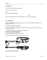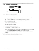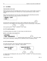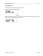
Line rider
© PRS 40 EZ REV A 03/16/06
190201_A
33
9.1.4 Linerider setup
Hardwired
Set the internal DIP switch to:
4-20 mA sensor
-
SETUP 1
Select the "HARDWIRED" from the following menu.
SENSORS/ LINERIDER/ HARDWIRED
9.1.5 Linerider Calibration
The zero point and the gain of the linerider must be set before operation.
Essential Information:
•
The units of measure shall be the same as load chart units.
•
Calibration should be completed after installation, crane modification, or anytime there is an
indication of inaccuracy.
•
Recommendations for system calibration:
Use single part line during calibration.
Note: Multiple parts of line are acceptable. (It only increases the amount of test load
recommended)
Pick a known test load as close as possible to the maximum rated load for line configuration.
The test load must include the hook block and all rigging.
1. Turn unit “on”.
2. Set the reeving to the actual parts of line configured.
3. Place hook block or headache ball on the ground, so there is no load on the hoist line.
4. Press
CALIBRATIONS/LINERIDER 0.
5. Press
. The display should show ,000 LB.
6. Pick a known test load as close as possible to the maximum rated load. SAE recommends the test
load should be accurate to
±
1%.
7. Press
CALIBRATIONS/LINERIDER ADJ.
8. Compare the known test load to the displayed load and adjust if necessary using the arrows on the
console.


