background image

24

BAT-F, BAT-Rail, BAT54, BAT300

Release 02 07/10

1.2.6

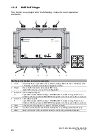
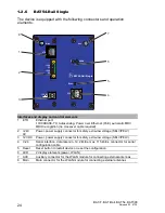
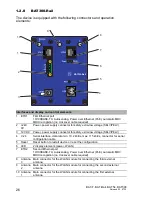
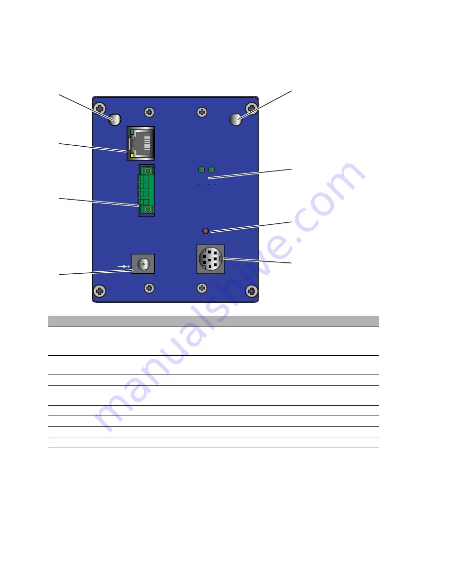
BAT54-Rail Single

The device is equipped with the following connectors and operation 
elements:

Interfaces and display and control elements
1

ETH

Ethernet port:
10/100BASE-TX, Autosensing, Power over Ethernet (PoE), automatic MDI/
MDIX recognition (no crossover cable required)

2

+24V


0V

Power, power supply connector for safety extra-low voltage (SELV/PELV)

3

12V DC

Power, power supply connector for safety extra-low voltage (SELV/PELV)

4

V.24

Serial interface, data rate min. 19.2 kbit/s, max. 115 kbit/s, connector for serial 
configuration cable

5

Reset

Reset button to restart device or reset the configuration

6

LED

2 display elements (power, WLAN)

7

AUX

Auxiliary connector for the WLAN module for connecting external antennas

8

Main

Main connector for the WLAN module for connecting external antennas

8

1

2

3

4

7

5

6

x

BAT54-Rail Single

Main

Aux

Reset

V.24

12V DC

+24V

0V

+24V

0V

ETH

WLAN

P

Summary of Contents for BAT300-F

Page 1: ...nt Uin 24VDC Uin 48VDC CLASS2 CLASS2 Iin 420mA Iin 170mA PoE WLAN 1 2 3 4 Pin TD RD TD RD Function 4 1 2 3 Ethernet 4 3 2 1 5 1 2 3 4 5 Pin 24V DC 0 V 0 V 24V DC N C Function Power LS DA P NC 4 1 2 3...

Page 2: ...atures described here are binding only if they have been expressly agreed when the contract was made This document was produced by Hirschmann Automation and Control GmbH according to the best of the c...

Page 3: ...2 2 BAT54 F Single 20 1 2 3 BAT54 F Client 21 1 2 4 BAT300 F 22 1 2 5 BAT54 Rail 23 1 2 6 BAT54 Rail Single 24 1 2 7 BAT54 Rail Client 25 1 2 8 BAT300 Rail 26 1 3 Device models 27 1 3 1 BAT54 F devic...

Page 4: ...2 BAT Rail 41 2 11 Connecting the supply voltage 42 2 11 1 5 pin M12 connector BAT F 42 2 11 2 4 pin terminal block BAT Rail 42 2 11 3 Power over Ethernet PoE power supply via the LAN cable 43 2 12 C...

Page 5: ...BAT F BAT Rail BAT54 BAT300 Release 02 07 10 5 3 Technical data 57 A Further support 65...

Page 6: ...duct or on the respective section of the documentation to which your special attention is being drawn Certified usage The device may only be employed for the purposes described in the catalog and tech...

Page 7: ...sure that the electrical installation meets local or nationally applicable safety regulations Warning Never insert sharp objects small screwdrivers wires etc into the inside of the product There is t...

Page 8: ...DEVICE WHEN IT IS ELECTRICALLY CHARGED DO NOT DETACH ANY CONNECTORS WHEN THE DEVICE IS ELECTRICALLY CHARGED DO NOT REMOVE THE LABELED HOUSING COVER The BAT F X2 FCC types are installed with a housing...

Page 9: ...ed in the care and use of appropriate safety equipment in accordance with the current standards of safety engineering X trained in providing first aid General safety instructions Electricity is used t...

Page 10: ...006 95 EG of the European Parliament and the council for standardizing the regulations of member states relating to electrical equipment to be used within specific voltage ranges but without applying...

Page 11: ...received including interference that may impede throughput Note This equipment has been tested and found to comply with the limits for a Class B digital device pursuant to part 15 of the FCC Rules The...

Page 12: ...Canadian ICES 003 Cet appareil num rique de la classe B est conforme la norme NMB 003 du Canada To reduce potential radio interference to other users the antenna type and its gain should be so chosen...

Page 13: ...10 13 About this manual The following manuals are available as PDF files on the CD ROM supplied X Installation user manual X Reference Manual Legend The symbols used in this manual have the following...

Page 14: ...ccess client with a WLAN interface for dualband operation in accordance with IEEE802 11b g and IEEE802 11a h and it is specially designed for outdoor use with protection class IP67 The BAT54 F can be...

Page 15: ...ant voltage supply 4 way for the BAT Client and a vibration resistant metal housing the devices provide high operational reliability 1 1 3 BAT54 types The BAT54 is a dual band industrial wireless LAN...

Page 16: ...representation of MIMO Multiple Input Multiple Output 1 1 5 BAT BG BGN types BAT BG BGN devices only support the use of the 2 4 GHz ISM wave band Note Note that the function descriptions for the BAT...

Page 17: ...zing also with 802 1x authentication X High performance operating system with a wide range of functions via MultiSSID VLAN Rapid SpanningTree RADIUS server IP router firewall DHCP server etc X Managem...

Page 18: ...on to the BAT wireless transmission system of the RS20 RS30 RS40 open rail range of switches the MICE range of switches the MACH range of backbone switches the EAGLE security system and products for t...

Page 19: ...Power supply connector for safety extra low voltage SELV PELV 5 pin M12 plug 5 LED 4 display elements power LS DA WLAN1 WLAN2 6 AUX 2 Auxiliary connector for the second WLAN module for connecting ext...

Page 20: ...ion no crossover cable required 4 Ethernet 1 First Ethernet port 4 pin M12 socket with D coding 10 100BASE TX Autosensing Power over Ethernet PoE automatic MDI MDIX recognition no crossover cable requ...

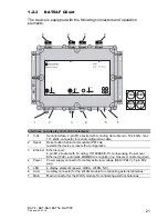
Page 21: ...r Ethernet PoE automatic MDI MDIX recognition no crossover cable required 4 Power Power supply connector for safety extra low voltage SELV PELV 5 pin M12 plug 5 LED 4 display elements power LS DA WLAN...

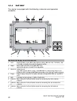
Page 22: ...able required 4 Power Power supply connector for safety extra low voltage SELV PELV 5 pin M12 plug 5 LED 4 display elements power LS DA WLAN NC 6 Antenna 3 Main connector for the WLAN module for conne...

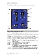
Page 23: ...dule for connecting external antennas 5 AUX 2 Auxiliary connector for the second WLAN module for connecting external antennas 6 V 24 Serial interface data rate min 19 2 kbit s max 115 kbit s connector...

Page 24: ...safety extra low voltage SELV PELV 3 12V DC Power power supply connector for safety extra low voltage SELV PELV 4 V 24 Serial interface data rate min 19 2 kbit s max 115 kbit s connector for serial c...

Page 25: ...r supply connector for safety extra low voltage SELV PELV 3 12V DC Power power supply connector for safety extra low voltage SELV PELV 4 V 24 Serial interface data rate min 19 2 kbit s max 115 kbit s...

Page 26: ...tage SELV PELV 4 V 24 Serial interface data rate min 19 2 kbit s max 115 kbit s connector for serial configuration cable 5 Reset Reset button to restart device or reset the configuration 6 LED 2 displ...

Page 27: ...oors also under extreme conditions BAT54 F X2 FCC Outdoors also under extreme conditions including environments with the danger of explosions BAT54 F X2 Outdoors also under extreme conditions includin...

Page 28: ...N rail and flat surface mounting Higher radio output and more stable network coverage through MIMO with 3 antennas BAT300 F FCC DIN rail and flat surface mounting Higher radio output and more stable n...

Page 29: ...doors also under extreme conditions BAT54 F BG Using the 2 4 GHz ISM wave band Outdoors also under extreme conditions BAT54 F X2 BG Using the 2 4 GHz ISM wave band Outdoors also under extreme conditio...

Page 30: ...up X Mounting outdoors BAT F X DIN rail mounting BAT Rail X Flat surface mounting X Mounting connecting external antennas X Connecting LAN and WLAN connectors X Connecting the supply voltage X Ground...

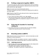
Page 31: ...l protection class IP 67 and that are certified for a temperature range from 30 C to 55 C 22 F to 131 F 2 4 Selecting the location for mounting setting up Set up mount the device in a location where t...

Page 32: ...and IEC 62305 Hirschmann recommends using the Hirschmann BAT Protector as a lightening protection see on page 62 Accessories Warning Installing this lightening protection element between an antenna a...

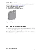
Page 33: ...meter 37 mm to 60 mm X Maximum permitted wind load 220 km h Figure 4 BAT F pole mounting set 2 6 DIN rail mounting BAT Rail Mount the device on a 35 mm DIN rail in accordance with DIN EN 60175 Attach...

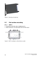
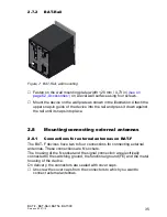
Page 34: ...02 07 10 Figure 5 Mounting on the DIN rail 2 7 Flat surface mounting 2 7 1 BAT F Prepare the drill holes at the installation point Mount the device on a flat surface with four M5 screws Figure 6 BAT...

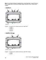
Page 35: ...nst the rail until it snaps into place 2 8 Mounting connecting external antennas 2 8 1 Connections for external antennas on BAT F The BAT F devices have two to four connections for connecting external...

Page 36: ...n TX RX N C GND Function V 24 1 2 3 4 Pin TD RD TD RD Function 4 1 2 3 Ethernet 4 3 2 1 5 1 2 3 4 5 Pin 24V DC 0 V 0 V 24V DC N C Function Reset Power LED Main 1 Main 2 AUX 1 AUX 2 BAT54 F IP67 WLAN A...

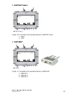
Page 37: ...Point Uin 24VDC Uin 48VDC CLASS2 CLASS2 Iin 420mA Iin 170mA PoE WLAN 1 2 3 4 Pin TD RD TD RD Function 4 1 2 3 Ethernet 4 3 2 1 5 1 2 3 4 5 Pin 24V DC 0 V 0 V 24V DC N C Function Power LS DA P NC 1 2 B...

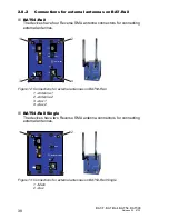
Page 38: ...Figure 12 Connections for external antennas on BAT54 Rail 1 Antenna 1 2 Antenna 2 3 Aux1 4 Aux2 BAT54 Rail Single The devices have two Reverse SMA antenna connectors for connecting external antennas...

Page 39: ...ernal antennas Figure 14 Connections for external antennas on BAT54 Rail Client 1 Main 2 Aux BAT300 Rail The devices have three Reverse SMA antenna connectors for connecting external antennas Figure 1...

Page 40: ...respective radio module 2 9 Connecting LAN and WLAN connectors In the Dual Band Industrial Access Point Access Client Access Bridge BAT54 Rail user manual you will find further information for connect...

Page 41: ...a minimum cross section of 4 mm2 to 6 mm2 for North America AWG 11 to AWG 9 including any terminal sleeve used and implement the grounding of the device via the screw connector Clamp the ground wire...

Page 42: ...M12 frame connector is electrically connected to the functional ground FE and to the metal housing of the device The supply voltage is electrically isolated from the housing Note For the BAT54 F the...

Page 43: ...the LAN cable This makes it unnecessary to have a separate power supply for every base station thus considerably reducing the work involved in the installation In the BAT F devices the voltage is inpu...

Page 44: ...full duplex mode State on delivery autonegotiation activated The TP connector is a 4 pin M12 female connector with D coding On delivery the connectors are sealed with cover caps The housing of the M1...

Page 45: ...Rail the 10 100 Mbit s twisted pair connections are RJ45 sockets 10 100 Mbit s ports enable the connection of terminal devices or independent network segments according to the IEEE 802 3 100BASE TX 10...

Page 46: ...the upper part of the housing cover on the device as shown in the following figure point 1 Do not try to remove the lower panel of the housing cover from the device Screw the device including the low...

Page 47: ...the voltage supply via the terminal block Pull the terminal block off the device and connect the voltage supply lines Mount the terminal block for the supply voltage on the front of the device Connect...

Page 48: ...re details 2 16 Installing external antennas External antennas are required to operate the access point You will find an overview of the antennas that are supported and can be connected along with the...

Page 49: ...BAT54 BAT300 Release 02 07 10 49 Open the configuration for the physical interface to which you are connecting the antenna On the Radio tab you will find an entry field for the antenna gain see the fo...

Page 50: ...tector installed devices from the antenna gain and enter the result in dB in the antenna gain field 2 17 Display elements After the operating voltage is applied the software starts and initializes its...

Page 51: ...for BAT54 Rail BAT54 Rail Client BAT300 Rail 1 Ethernet port link status LS BAT54 F Single WLAN P LS DA 2 LS DA 1 BAT54 F Client WLAN LS DA P NC BAT300 F LS DA P WLAN NC BAT54 F LS DA P WLAN 2 WLAN 1...

Page 52: ...n red LED Power Green on continuously Device is ready for operation Red blinking slowly Charge lock active see Dual Band Industrial Access Point Access Client Access Bridge BAT54 Rail user manual Gree...

Page 53: ...you have to reconfigure the device independently of any existing settings or if no connection to the device configuration can be made X Device restart soft reset the button is pressed for less than 5...

Page 54: ...set button see 1 in the following figure is located on the front plate of the device Figure 21 Reset button on BAT Rail 2 19 Basic set up Information on the basic settings of the device can be found i...

Page 55: ...M12 is not designed to be used with BAT F devices If you do not adhere to this warning the ACA21 M12 could be destroyed Use the ACA11 M12 if you want to use an AutoConfiguration Adapter for your BAT F...

Page 56: ...device from the DIN rail press the device downwards and pull it out from under the DIN rail Figure 22 Removal from the DIN rail Figure Pin Function 1 CTS Clear to send 2 RTS Request to send 3 RxD Rec...

Page 57: ...ce up to 8 SSIDs per WLAN interface 1 x LAN port 10 100BASE TX Autosensing BAT54 Rail 2 x WLAN interfaces up to 8 SSIDs per WLAN interface 2 x LAN ports 10 100BASE TX Autosensing BAT54 Rail Single 1 x...

Page 58: ...BAT300 F Three antenna connections BAT54 Rail Four Reverse SMA antenna connections sockets BAT54 Rail Single Two Reverse SMA antenna connections sockets BAT54 Rail Client Two Reverse SMA antenna conne...

Page 59: ...MBit s MCS7 15 40 MHz max 5 GHz power output at antenna input 802 11a h 18 dBm 6 to 24 MBit s 17 dBm 36 MBit s 16 dBm 48 MBit s 15 dBm 54 MBit s 802 11n 18 dBm 6 5 13 MBit s MCS0 8 20 MHz 10 dBm 65 1...

Page 60: ...FCC IEC 60079 0 chap 6 2 Shock resistance test with 1kg mass dropped from 0 7 m Housing cover only removeable with tool EN 300 328 Electromagnetic compatibility and radio spectrum matters ERM bandwidt...

Page 61: ...tu IT h 943 926 521 BAT54 Rail Client FCC 10 0 W 34 1 Btu IT h 943 926 522 BAT300 Rail 10 0 W 34 1 Btu IT h 943 989 001 BAT300 Rail FCC 10 0 W 34 1 Btu IT h 943 989 101 BAT300 F 10 0 W 34 1 Btu IT h 9...

Page 62: ...band antennas DIN rail mounting material Three 3 dBi dipole dual band antennas DIN rail mounting material Name Order number ACA11 M12 AutoConfiguration Adapter for M12 connection 943 972 001 ACA11 min...

Page 63: ...onic systems in railway vehicles EN 55022 2006 A1 2007 IT equipment radio interference characteristics EN 60079 15 Electrical equipment for explosive gas atmospheres part 15 Construction testing and m...

Page 64: ...ws the status of the device certifications Standard EN 60079 15 ATEX95 pending Table 10 Certifications see www hirschmann ac com for current status For further information on other notifications or ce...

Page 65: ...nter In the long term excellent products alone do not guarantee a successful customer relationship Only comprehensive service makes a difference worldwide In the current global competition scenario th...

Page 66: ......

Reviews: