28
3.2 Temperature Measurement Using a Thermocouple (K)
Quick Start Manual
5.
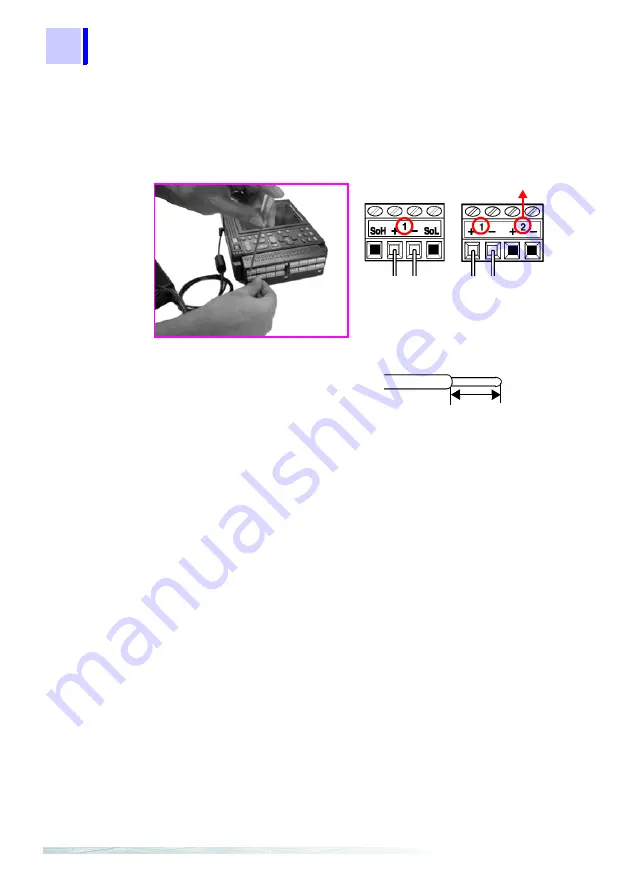
Using the supplied flat blade screwdriver, connect the thermocouple (K)
to channel 1 on the terminal board.
Be sure that the polarity of the cable connection is correct.
See Section 2.2 "Connecting Measurement Cables" (page 25) of Instruction Manual.
Recommended Lead Wire
6.
Replace the terminal board cover, to protect the terminal board, and for
safety. If the input terminals are exposed to a strong wind, this can upset
the thermal balance of the input unit, and cause incorrect readings.
7.
Attach the thermocouple (K) to the object whose temperature is to be
measured.
8.
Turns on the power switch.
See Section 2.3 "Powering On/Off" (page 31) of Instruction Manual.
9.
Set the parameters of this instrument.
GND
8420-51
8422-51
8421-51
GND
Channel Number
Wire diameter
: 0.32 mm
Wire stripping length : 5 mm
単線
撚線
5 mm
Summary of Contents for 8420-51
Page 1: ...MEMORY HiLOGGER QUICK START MANUAL 8420 51 8421 51 8422 51 ...
Page 2: ......
Page 4: ...ii Quick Start Manual Contents ...
Page 7: ...3 1 2 3 4 5 6 7 8 9 10 11 Identification of Controls and Indicators 1 ...
Page 12: ...8 1 1 Identification of Controls and Indicators Quick Start Manual ...
Page 16: ...12 2 3 Waveform Screen Quick Start Manual ...
Page 50: ...46 3 3 Integrating the Pulse Output from a Power Meter Quick Start Manual ...


