Operating instructions
en
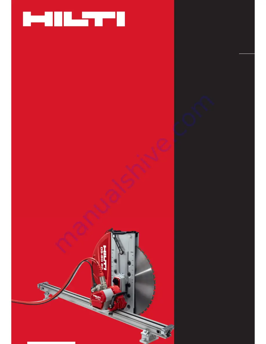
DS TS20-E
Printed: 08.07.2013 | Doc-Nr: PUB / 5069686 / 000 / 01
Page 1: ...Operating instructions en DS TS20 E Printed 08 07 2013 Doc Nr PUB 5069686 000 01...
Page 2: ...s warranty tools 34 ORIGINAL OPERATING INSTRUCTIONS DS TS20 E 3 480 V electric wall saw It is essential that the operating instructions are read before the machine is operated for the first time Alwa...
Page 3: ...Power cable Control cable Water hose Transport trolley saw head Blade guard center section Blade guard side section Guide rail with end stop Accessory box with rail support and toolbox Transport troll...
Page 4: ...use and reduce the risk of electric shock 1 3 1 2 1 1 Personal Safety Stay alert watch what you are doing and use com mon sense when operating a power tool Do not use a tool while tired or under the...
Page 5: ...tools Use only accessories that are recommended by the manufacturer for your model Accessories that may be suitable for one tool may become hazardous when used on another tool Service Tool service mu...
Page 6: ...auses dust j Keep children and other persons away from the work ing area k Do not allow other persons to touch the machine or the extension cord l Avoid unfavorable body positions Make sure you work f...
Page 7: ...to the specification given on the type plate j Electric cables and their plug connectors must be kept dry When not in use close power outlets with the cover provided k Use only extension cables which...
Page 8: ...2 5 2 4 position The operator must take additional precauti ons fit a cover plank of wood boards etc where necessary Never enter the danger area e g to change the saw blade remove the blade guard sid...
Page 9: ...lectric Shock Connect only to properly grounded outlets 359292 WARNING Disconnect Power and wait 5 minutes before opening for service 359275 Do not touch metal parts of saw head and E box during opera...
Page 10: ...out suitable pre treatment is problematical In addition to the following recommended pre treat ment procedures the applicable national regulations must be observed when disposing of drilling or saw in...
Page 11: ...that may release hazardous or explosive dust or vapors during the cutting process Do not cut inflammable materials 7 Overhead sawing is possible when additional pre cautionary measures are taken For t...
Page 12: ...class IP 65 Saw blade diameter 24 to 48 600 mm to 1200 mm Max cutting depth 21 53 cm Weight 82 lb 37 kg Dimensions l w h 14 8 17 3 12 6 37 5 44 32 cm Operating storage temperature 5 to 122 F 15 C to...
Page 13: ...mm Weight loaded 267 9 lb 200 7 lb 121 5 kg 91 kg Max permissible total weight 330 8 lb 330 8 lb 150 kg 150 kg With 3 3 ft 1 m rail Height with 7 5 ft 2 3 m rail 97 245 cm Contents in accordance with...
Page 14: ...to be carried out been approved in full by the site engineer or architect 4 2 1 2 3 4 5 4 1 Electric power supply fuse rating CAUTION Irrespective of whether using mains power or genera tor power alw...
Page 15: ...le even when the bypass valve is fully closed Connecting the power supply NOTE Operating the main swith several times in quick suc cession will cause the electric supply to be temporarily interrupted...
Page 16: ...ure to observe the spacing shown may cause the saw to wander off course and in extreme situations may result in failure of the anchor fastenings Adequately dimensioned and correctly installed fas teni...
Page 17: ...lamp to the rail 2 Position the rail with fitted rail clamp on the rail sup port and close the clamping plate 3 Turn the rail support until at right angles to the rail and then tighten the clamping pl...
Page 18: ...5 8 49 10 53 11 55 13 59 16 65 19 72 15 10 69 7 21 9 21 10 21 12 22 15 22 18 22 20 11 35 5 85 7 80 8 77 10 72 13 65 16 57 25 12 15 4 43 6 30 7 24 9 12 11 94 14 76 30 13 13 2 94 4 74 5 63 7 43 10 12 12...
Page 19: ...eve Mounting the saw head NOTE The DS FCA 110 flush cutting flange should be mount ed on the saw head for flush cutting applications 1 Press the release button on the locking lever and push the lockin...
Page 20: ...rip the plug and not the cable Fit the protective cap immediately Do not use the plug as a grip or carrying handle Do not allow the cables to become tangled and place them carefully so that the plug c...
Page 21: ...ting the wall saw each time always check the mounting flange and saw blade for damage cracks or discoloration caused by overheating and clean the saw blade if it has been oiled or greased 1 Position t...
Page 22: ...wing Use the DS FCA flush cutting flange and flush cut ting blade guard available as accessories for flush cutting applications CAUTION Remove the side section only immediately before begin ning a cor...
Page 23: ...gaged Move the locking levers back and forward slightly to check that they are engaged correctly 6 The power and control cables and water hoses must be laid out connected correctly and the locking sle...
Page 24: ...ess in an emergency Leave pressed in when setting up or changing blades etc Turn knob in direction of arrow to release display position Reset switch for Output Stop Reset must be pressed after releasi...
Page 25: ...tion 4 Operate the direction of movement control switch or 5 Turn the starting switch to the Start position and hold it there 6 When reversal of control direction has been successful L__R is shown in...
Page 26: ...at reduced power e g 60 This prevents the blade wandering off course and ensures a straight cut 5 4 5cm 2 ll lll l max 24 9 32 13 42 18 48 21 max 600mm 23cm 800mm 33cm 1000mm 43cm 1200mm 53cm 10 15cm...
Page 27: ...t of equipment after finishing work or before long breaks between periods of use 3 Do not allow dirt and slurry to dry out and adhere to the parts 4 When cleaning pay particular attention to the opera...
Page 28: ...d have it repaired if necessary Check the water flow and replace the mesh filter at the water supply connection if necessary Power supply Check the switches and indicator lamps for correct operation a...
Page 29: ...cooling Er51 off due to overheating too warm water flowing restart Er52 Return the saw head to Hilti Er53 Service Symbol 11 lights Er20 Machine cannot be Temperature sensor in the Return the saw head...
Page 30: ...Symbol 15 lights Er42 Machine cannot be switched Electric power is inadequate Check the electric supply Er43 on or switches itself off Return the power supply to Hilti Service Symbol 15 blinks Sr45 W...
Page 31: ...Er85 Machine cannot be switched Contactor K1 or K2 in the Return the power supply Er86 on power supply is faulty to Hilti Service Er87 Er88 Display Er91 The machine doesn t function Safety loop for Ou...
Page 32: ...l hazards that may be encountered Repairs to electrical components may be carried out only by trained electrical specialists NEVER open the covers on the machine while on a construction site The capac...
Page 33: ...ignation Use 284808 DS R100 L rail Saw guidance 3 3 ft 284809 DS R200 L rail Saw guidance 6 5 ft 284810 DS R230 L rail Saw guidance 7 5 ft 371703 DS ES L end stop Safety stop for saw head 207137 DS CP...
Page 34: ...of normal wear and tear are not covered by this warranty Additional claims are excluded unless stringent national rules prohibit such exclusion In particular Hilti is not obligated for direct indirect...
Page 35: ...35 Printed 08 07 2013 Doc Nr PUB 5069686 000 01...
Page 36: ...2342111 Fax 423 2342965 www hilti com 401513 A2 Hilti registered trademark of Hilti Corp Schaan W 3081 I 0709 I 1 en_USA I 1 Printed in Liechtenstein 2009 Right of technical and programme changes rese...