


DS-PRI120 Security Radar User Manual
UM DS-PRI120 091720NA
49
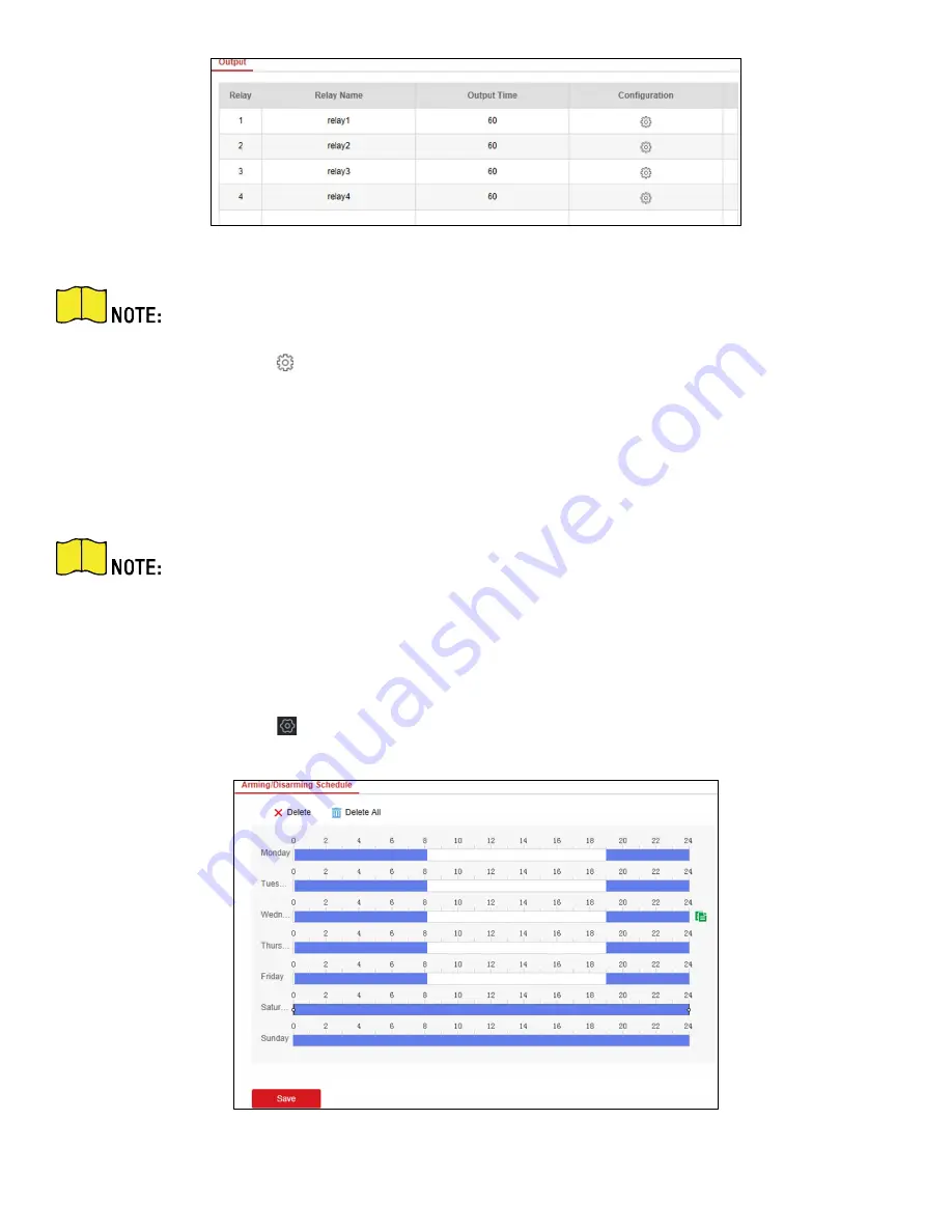
Figure 8-4 Relay
You can also click
E-
map → Edit → Radar Settings → Alarm Output
to open/close the relay.
2.
Select an relay, and click
to enter the page.
3.
Edit the relay name, and output time.
4.
Set relay linkage. Link the relay with alarm event, system event, and arming/disarming operation.
5.
Optional:
Check
Enable Zone Tracking
. When enabled, after the relay-linked zone is triggered by an alarm,
the relay will remain open until the target exits the zone or the alarm is manually closed.
After the zone tracking is turned on, if only the zone is selected in the alarm event, the relay
output time is based on the time when the alarm triggered in the zone.
6.
Click
OK
to save.
8.5
Set Arming/Disarming Schedule
1.
Select the radar and click
in the client software, or enter the IP address of the radar in the address bar of
the Web browser. Click
Smart Rule Settings → Arming/Disarming Schedule
to enter the page.
Figure 8-5 Arming/Disarming Schedule