background image

DS-K1201 Fingerprint Card Reader 

Chapter 2


Installation 

2.1


Introduction for DIP Switch 

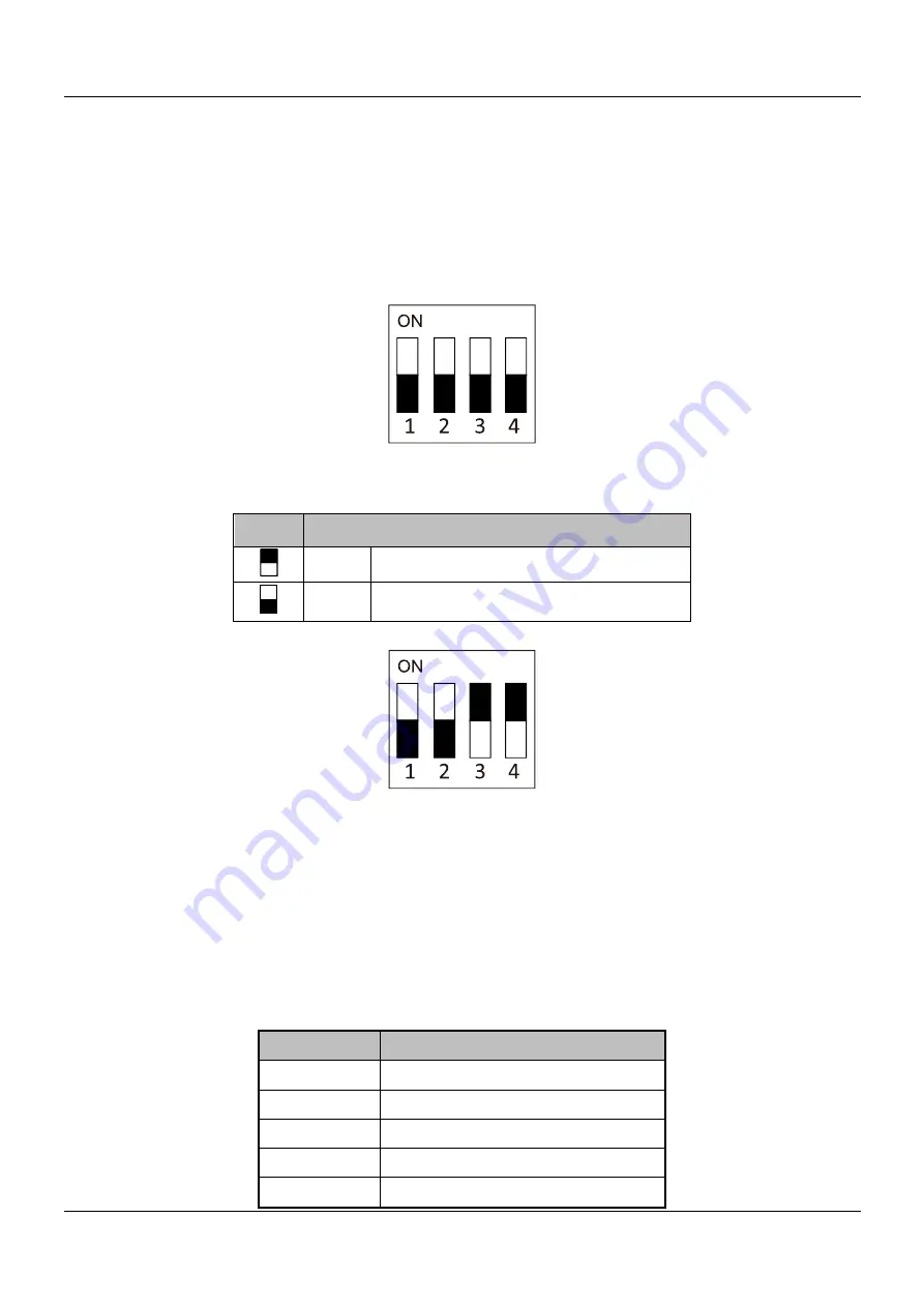
The DIP switch module is shown below. The No. of DIP switch from left to right is 1 
to 4, representing the RS-485 address.   


Figure 2-1


DIP Switch Module 

Table 1-2


Description of DIP Switch 

Icon 

Description 


Represent ON in binary mode 


Represent OFF in binary mode 

For example, the binary value of the following status is 1100. 


Figure 2-2


DIP Switch Module 

Note:

  The  DIP  switch  of  RS-485  address  should  reach  the  access  control  devices 

requirements. For different access control devices, the DIP switch addresses may be 
different. 

2.2


Definition of Cable 

The description of 5 cables is shown below. 

Table 1-3


Description of Cables 

Color 

Description 

Blue 

RS-485 - 

Yellow 

RS-485 + 

Red 

PWR (DC +12V) 

Black 

GND (Power Grounding) 

Black 

GND (RS-485 Grounding) 

Summary of Contents for DS-K1201A Series

Page 1: ...DS K1201A Series Fingerprint Card Reader User Manual...

Page 2: ...ties of their respective owners Disclaimer TO THE MAXIMUM EXTENT PERMITTED BY APPLICABLE LAW THE PRODUCT DESCRIBED WITH ITS HARDWARE SOFTWARE AND FIRMWARE IS PROVIDED AS IS WITH ALL FAULTS AND ERRORS...

Page 3: ...ected stored and processed To protect data the development of Hikvision devices incorporates privacy by design principles For example for device with facial recognition features biometrics data is sto...

Page 4: ...receiving antenna Increase the separation between the equipment and receiver Connect the equipment into an outlet on a circuit different from that to which the receiver is connected Consult the dealer...

Page 5: ...ure that user can use the product correctly to avoid danger or property loss The precaution measure is divided into Warnings and Cautions Warnings Neglecting any of the warnings may cause serious inju...

Page 6: ...occur otherwise which is not a malfunction however and affecting the endurance of sensor at the same time Please use the provided glove when open up the device cover avoid direct contact with the devi...

Page 7: ...n 1 1 1 Product Overview 1 1 2 Product Appearance 1 Chapter 2 Installation 2 2 1 Introduction for DIP Switch 2 2 2 Definition of Cable 2 2 3 Wiring Cables 3 2 4 Installing Card Reader 3 Chapter 3 Soun...

Page 8: ...communicates with access controller via the RS 485 protocol And a built in tamper proof module helps to protect card reader from malicious damage NFC tag anti cloning is also supported 1 2Product Appe...

Page 9: ...nary mode 0 Represent OFF in binary mode For example the binary value of the following status is 1100 Figure 2 2 DIP Switch Module Note The DIP switch of RS 485 address should reach the access control...

Page 10: ...or RS 485 address For Details refer to 2 1 Introduction for DIP Switch 2 Wire the cable between the controller and the card reader as shown below Figure 2 3 Wiring for RS 485 Communication Mode 2 4Ins...

Page 11: ...the cables between the controller and the card reader For details refer to 2 3 Wiring Cables 3 Unscrew the screw at the bottom of the card reader 4 Buckle the card reader up to the plate 5 Fasten the...

Page 12: ...d the LED indicator to indicate different statuses You can refer to tables below for detailed information Table 1 4 Description of Prompt Sound Sound Prompt Description One beep Swiping card prompt Fo...

Page 13: ...inking For Card Fingerprint authentication prompt for pressing the fingerprint after swiping the card The operation of configuring the fingerprint Solid green for 2s The operation of swiping card is v...

Page 14: ...Scanning The figures of scanning fingerprint displayed below are wrong Environment The scanner should avoid direct high light high temperature humid conditions and rain When it is dry the scanner may...

Page 15: ...8 UD22704B...

Reviews: