background image

10 


through tab pages. It will also bring up the Channel & OSD Position settings. 


4GHI/ESC

: (1) Enter numeral “4”

(2) Enter letters “GHI”


                   (3) Exit and back to the previous menu 


5JKL/EDIT

:  (1) Enter numeral “5”;  (2) Enter  letters  “JKL”

(3)  Delete  characters before 

cursor;   


                   (4)Select the checkbox and ON/OFF switch; (5) Start/stop record clipping in playback 


6MNO/PLAY

:  (1) Enter numeral  “6”;  (2) Enter letters  “MNO”;  (3)  Playback, for direct 

access to playback interface


7PQRS/REC

: (1) Enter numeral “7”; (2) Enter letters “PQRS”

(3) Manual record, for 

direct access to manual record interface; manually enable/disable record


8TUV/PTZ

:  (1) Enter numeral  “8”

(2) Enter letters  “TUV”

(3) Access PTZ control 

interface


9WXYZ/PREV

:  (1) Enter numeral  “9”

(2) Enter letters  “WXYZ”; (3) Multi-camera 

display in live view.


0/A

:


(1) Enter numeral  “0”

(2) switch between input methods (upper and lowercase 

alphabet, symbols and numeric input) 

4.


SHIFT: 

Switch of compound keys between the numeric/letter input and functional control. 


5.


Control Buttons:   


Directional buttons:

 In menu mode, the 

direction

 buttons are used to navigate between 

different fields and items and select setting parameters. In playback mode, the 

Up

 and 

Down


buttons are used to speed up and slow down record play, and the 

Left

 and 

Right

 buttons are 

used to select the recording 30s forwards or backward

s. In live view mode, these buttons can be 

used to cycle through channels.   


Enter:

 The

 Enter

 button is used to confirm selection in menu mode; or used to select


checkbox fields and ON/OFF switch. In playback mode, it can be used to play or pause the 
video. In single-frame play mode, pressing the 

Enter

 button will advance the video by a 

single frame. And in auto sequence view mode, the buttons can be used to pause / resume 
auto sequence.   

6.


USB Interface:

 Connects USB mouse or USE flash memory devices.


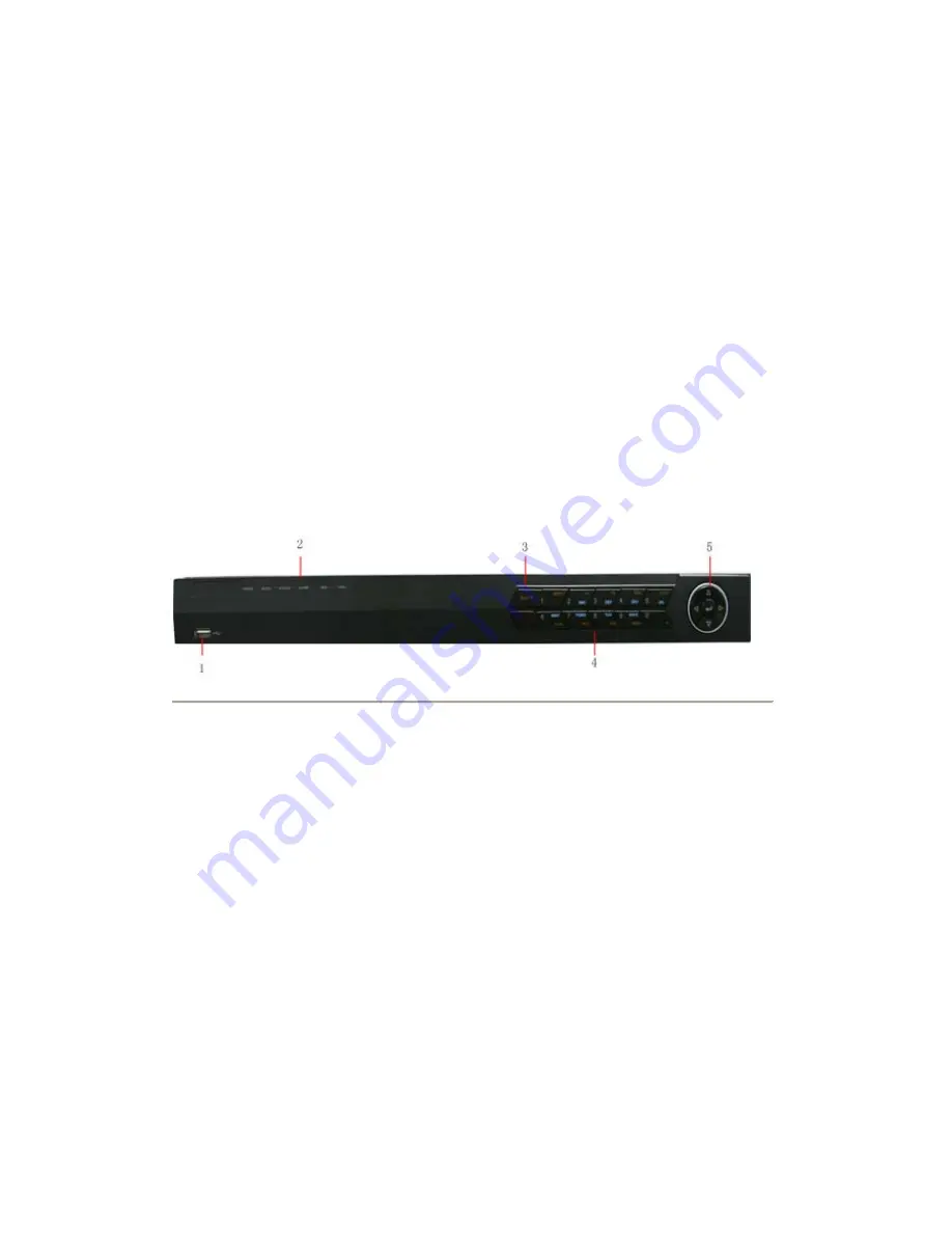
Figure5. DS-7608NI-S DVR Front Panel     


The controls on the front panel include:   

1.


USB Interface:

 Connect USB mouse or USE flash memory devices. 

2.


Status Indicators


POWER

: the POWER indicator turns green when NVR is powered up. 


READY

: the indicator lights in green when the device is running normally. 


STATUS

: the indicator: 1. Lights in green when the IR remote control is enabled; 2. Lights in 

red when the compound key (SHIFT) is used. 


ALARM

: the indicator lights in red when there is sensor alarm occurring. 


HDD

: the indicator flickers in red when HDD is reading/writing. 


Tx/Rx

: TX/RX indicator flickers green when network connection is functioning normally. 

3.


SHIFT

: Switch of compound keys between the numeric/letter input and functional control. 

4.


Compound Buttons: 


1 MENU: 

(1) Enter numeral “1”; (2) Access the main menu interface.


2ABC/F1

: (1) Enter numeral “2”; (2) Enter letters “ABC”; (3) The F1 button when used in a 

list field will select all items on the list. In PTZ Control mode, it will turn on/off PTZ light.


3DEF/F2

:


(1) Enter numeral “3”; (2) Enter letters “DEF”; (3) The F2 button is used to cycle 

through tab pages. It will also bring up the Channel & OSD Position settings.


4GHI/ESC

: (1) Enter numeral “4”; (2) Enter letters “GHI”; (3) Exit and back to the 

previous menu.


5JKL/EDIT

: (1) Enter numeral “5”; (2) Enter letters “JKL”; (3) Delete characters before 

cursor; (4)Select the checkbox and ON/OFF switch; (5) Start/stop record clipping in 
playback.


6MNO/PLAY

: (1) Enter numeral “6”; (2) Enter letters “MNO”; (3) Playback, for direct 

access to playback interface

www.cctvireland.ie

[email protected]

Summary of Contents for DS-7604 Series

Page 1: ...DS 7600 Series DVR USER MANUAL Version 1 2 0 www cctvireland ie shop cctvireland ie HIKVision DS 7604 DS 7608 DS 7616 Analogue CCTV Recorder USER MANUAL ...

Page 2: ...ANTABILITY AND FITNESS FOR A PARTICULAR PURPOSE REGARDING THE HIKVISION SOFTWARE HIKVISION DOES NOT WARRANT GUARANTEE OR MAKE ANY REPRESENTATIONS REGARDING THE USE OR THE RESULTS OF THE USE OF THE HIKVISION SOFTWARE IN TERMS OF ITS CORRECTNESS ACCURACY RELIABILITY CURRENTNESS OR OTHERWISE THE ENTIRE RISK AS TO THE RESULTS AND PERFORMANCE OF THE HIKVISION SOFTWARE IS ASSUMED BY YOU THE EXCLUSION OF...

Page 3: ...ropean Union For proper recycling return this product to your local supplier upon the purchase of equivalent new equipment or dispose of it at designated collection points For more information see www recyclethis info 2006 66 EC battery directive This product contains a battery that cannot be disposed of as unsorted municipal waste in the European Union See the product documentation for specific b...

Page 4: ...etely enclosed power supply of the proper rated voltage and current No user serviceable parts inside the power supply System Grounding Earthing To avoid shock ensure that all AC wiring is not exposed and that the earth grounding is maintained Ensure that any equipment to which this device will be attached is also connected to properly wired grounded receptacles and are approved medical devices Pow...

Page 5: ...cling Please recycle batteries Thermal and Mechanical Injury Some components such as heat sinks power regulators and processors may be hot care should be taken to avoid contact with these components Electro Magnetic Interference This equipment has not been tested for compliance with emissions limits of FCC and similar international regulations This device is not and may not be offered for sale or ...

Page 6: ...4NI S DS 7604NI S M and DS 7608NI S series DVR This manual may contain several technically incorrect places or printing errors and the content is subject to change without notice The updates will be added into the new version of this manual We will readily improve or update the products or procedures described in the manual www cctvireland ie shop cctvireland ie ...

Page 7: ...ajor shocks or jolts to the unit as a result of dropping it may cause damage to the sensitive electronics within the unit Use the DVR in conjunction with an UPS if possible Power down the unit before connecting and disconnecting accessories and peripherals A factory recommended HDD should be used for this device Improper use or replacement of the battery may result in hazard of explosion Replace w...

Page 8: ...Initializing Record Settings 28 Scheduling a Recording 29 Starting a Manual Recording 30 Protect Recorded Files 31 Lock Unlock Recorded Files 31 Set HDD to Read Only 31 Configuring Advanced HDD Settings 32 Setting up HDD Redundancy 32 C H A P T E R 5 35 Playback 35 Video Playback 36 Playback Interface 36 Play Back by Video Search 36 Playback by Event Search 37 Playback in Live View Mode 39 Playbac...

Page 9: ...ttings 72 Set up Privacy Mask 73 Adjust Display Settings 74 C H A P T E R 1 1 75 HDD Management 75 Manage HDDs 76 Initializing HDDs 76 Setting Network HDD 76 Set HDD Groups 78 Set HDD Status 78 Configure HDD Alarms 80 C H A P T E R 1 2 82 DVR Management 82 Configure System Settings 83 Configuring General Settings 83 Configuring Advanced Settings 83 RS 232 Port Settings 84 Managing User Accounts 85...

Page 10: ...6 C H A P T E R 1 Introduction www cctvireland ie shop cctvireland ie ...

Page 11: ... Scheduled and event recording parameters configurable per individual camera Encoding for both audio video composite stream and video stream audio and video synchronization during composite stream encoding Local Monitoring DS 7604HI S supports 1 4 9 division video live view with adjustable cameras order for display DS 7604 NI S and DS 7604NI S M support 1 4 division video live view DS 7608 NI S su...

Page 12: ...bnormal video in out format unmatched illegal access network disconnection IP conflict hard disk error and hard disk full Various alarm response actions supported camera recording relay out on screen warning audible warning and upload to center etc Auto recovery from exceptions Other Local Functions Control of DVR via front panel keys mouse IR control and special keyboard Three level user manageme...

Page 13: ...ntrols on the front panel include 1 Status Indicators POWER the POWER indicator turns green when DVR is powered up STATUS the indicator 1 Lights in green when the compound key SHIFT is used 2 Flickers in red when the HDD is reading writing Tx Rx TX RX indictor flickers green when network connection is functioning normally 2 IR Receiver operation by IR remote control 3 Compound Buttons 1 MENU 1 Ent...

Page 14: ...ode pressing the Enter button will advance the video by a single frame And in auto sequence view mode the buttons can be used to pause resume auto sequence 6 USB Interface Connects USB mouse or USE flash memory devices Figure5 DS 7608NI S DVR Front Panel The controls on the front panel include 1 USB Interface Connect USB mouse or USE flash memory devices 2 Status Indicators POWER the POWER indicat...

Page 15: ...e recording 30s forwards or backwards In live view mode these buttons can be used to cycle through channels Enter The Enter button is used to confirm selection in menu mode or used to select checkbox fields and ON OFF switch In playback mode it can be used to play or pause the video In single frame play mode pressing the Enter button will advance the video by a single frame And in auto sequence vi...

Page 16: ...re installed correctly and the polarities of the batteries are not reversed 2 Batteries are fresh and not out of charge 3 IR receiver is not obstructed 4 No fluorescent lamp is used nearby Using a USB Mouse A regular 3 button Left Right Scroll wheel USB mouse can also be used with this DVR To use a USB mouse 1 Plug USB mouse into one of the USB ports on the front panel of the DVR 2 The mouse shoul...

Page 17: ...t of the cursor Enter Confirm selection ESC Exit Soft Keyboard Figure8 Soft Keyboard Buttons Rear Panel Figure9 Rear Panel of DS 7604HI S No Item Description 1 USB Interface Connector for USB devices 2 VIDEO IN BNC connectors for video input 3 VIDEO OUT BNC connector for video output If VGA output has been connected then the VIDEO OUT port provides no output VIDEO OUT1 is main video out and VIDEO ...

Page 18: ...B devices 2 VIDEO OUT BNC connector for video output If VGA output has been connected then the VIDEO OUT port provides no output 3 AUDIO IN RCA connectors for analog audio input 4 AUDIO OUT RCA connector for audio output 5 LAN Connector for LAN Local Area Network 6 VGA DB15 connector for VGA output Display local video output and menu 7 RS 485 Interface Connector for RS 485 devices T T pin connects...

Page 19: ...D Ground needs to be connected when DVR startup Figure12 Rear Pane of DS 7608NI S No Item Description 1 USB Interface Connector for USB devices 2 VIDEO OUT BNC connector for video output 3 AUDIO IN RCA connectors for analog audio input 4 AUDIO OUT RCA connector for audio output 5 LAN Connector for LAN Local Area Network 6 VGA DB15 connector for VGA output Display local video output and menu 7 RS 4...

Page 20: ...16 C H A P T E R 2 Getting Started www cctvireland ie shop cctvireland ie ...

Page 21: ...shown in Figure 1 by clicking on Menu Shutdown Figure1 Shutdown Menu 2 Select the Shutdown button 3 Click the Yes button Rebooting and Locking Your DVR While in the Shutdown menu Figure 12 you may also reboot or lock your DVR Locking your DVR will return you to the Live View mode which will require a user name and password to exit out of it The Reboot button will reboot your DVR To reboot or lock ...

Page 22: ...Password text box By default the password is 12345 4 To change the admin password check the New Admin Password checkbox Type new password and confirm it in the given text boxes 5 Click the Next button This will take you to the General Settings dialog box shown in Figure 4 Figure4 General Settings 6 Click the Enter button to enter the General Settings interface 7 Select the language output standard...

Page 23: ...log box shown in Figure 6 Figure6 HDD Management 12 To access HDD management interface click the Enter button 13 If a new HDD has been recently installed select the HDD from the list to initialize it Initializing the HDD will format and remove all data from it 14 After the HDD has been initialized click the OK button which will take you back to the Setup Wizard window 15 Click Next button to enter...

Page 24: ...lect the channel or all under Copy To and click the Copy button 21 Click Next button to access the Network Settings dialog box shown in Figure 10 Figure10 Network Settings 16 To configure network settings click the Enter button 17 Enter the IP Address Subnet Mask and Default Gateway settings 18 Click OK button to return to the Setup Wizard 19 If all the settings have been entered click Done to fin...

Page 25: ...by clicking the MENU button on the remote or front panel You can also go to the Menu window by right clicking with the mouse and clicking the Menu button 2 Click the Settings icon 3 Click the General icon You will be taken to the General Settings window as shown in Figure 11 Figure11 General Settings 4 Enter the correct date and time in System Time 5 Click the Apply button to save the setting www ...

Page 26: ...22 C H A P T E R 3 Live View www cctvireland ie shop cctvireland ie ...

Page 27: ...Single Camera in right click menu 2 Multi camera View By Front Panel Remote Press PREV button By Mouse Select Multi Camera in right click menu 3 Manual Switch By Front Panel Remote Press the Left arrow button to access the previous screen press the Right arrow button to access next screen By Mouse Select Next Screen in right click menu 4 Auto Sequence By Front Panel Remote Press Enter button By Mo...

Page 28: ...ing Start Auto switch function Figure2 Live View Mouse Menu Digital Zoom To use digital Zoom in Live View mode 1 Right click the mouse in Live View mode 2 Select Digital Zoom from drop down submenu 3 Left click and drag the red box to the desired area for zooming The zoomed image will be magnified by 4 times An example is given in the following figure Figure3 Digital Zoom Display Click Menu Settin...

Page 29: ...DEO OUT2 is used as the auxiliary output which only allows user to access the full screen live view for channel 01 as configured in the Live View Display and no operation is accessible When there is no VGA display connected to DVR the main video output port VIDEO OUT1 will be used as the main output and all operations are accessible the auxiliary video output port VIDEO OUT2 is used as the auxilia...

Page 30: ...n Vout 3 Use the direction buttons on front panel to move to the display pane for setting press the Enter button to confirm the selection 4 Use the direction buttons on front panel to select the camera you want to be view in the display pane The option indicates no display of camera 5 Press Enter button to confirm the selection Note DS 7604NI S M DS 7604NI S and DS 7608NI S models provide no analo...

Page 31: ...27 C H A P T E R 4 Record Settings www cctvireland ie shop cctvireland ie ...

Page 32: ... box shown in Figure 1 Figure1 General Record Settings 2 Select the camera you want to configure Note DS 7604NI S M DS 7604NI S and DS 7608NI S models provide no analog camera connection please select IP Cameras for configuration 3 Configure the following settings Encoding Parameters Set the encoding parameters to be Normal or Event Stream Type Set the stream type to be Video or Video Audio Resolu...

Page 33: ...e refer to Section 12 4 Redundant HDD for specific settings Record Audio Enable or disable audio record of the selected camera Click OK to finish settings and return to the previous menu 5 Press the 3DEF F2 button on DVR front panel to select the Advanced tab to access the Advanced Settings submenu shown in Figure 3 6 Enable or disable the Overwrite setting Enabling the Overwrite setting will caus...

Page 34: ...ings about motion detection and alarm recordings please refer to the Configuring Alarms 9 Click the OK button to finish configuration 10 Repeat Steps 3 9 for other cameras or copy settings from one schedule to the others under the Copy To item 11 Click OK to finish configuration and save the schedule settings Note The Event encoding parameters will take effect when motion detection or alarm happen...

Page 35: ... desired recording by entering search parameters Search parameters include Camera ID Video File Type and Start End Time 3 Click the Search button A list of record files see Figure 7 matching the search parameters will be displayed 4 Select the file you want to lock unlock 5 Click the Lock button to lock file If the file is already locked click the Unlock button to unlock file Locked files will be ...

Page 36: ...rder to enable recordings on that particular disk again you must set the HDD to R W Read Write in the HDD Property Settings menu If multiple HDDs are used the DVR will automatically record to the next HDD that is not set to read only Configuring Advanced HDD Settings Setting up HDD Redundancy To avoid unexpected failures of hard disk drives and enhance the reliability it s recommended to set up HD...

Page 37: ...ous menu Note 1 When the selected HDD is set to redundancy it is used for redundant recording only 2 Make sure at least one HDD installed in DVR has been set to R W read write Figure11 HDD Settings 7 Click Menu Settings Record Setting to access the Record Settings dialog box 8 Click the General tab 9 Select the Camera to be used for redundancy 10 Move the cursor to More Settings and click the Set ...

Page 38: ...ure12 Additional Record Settings 11 Set Redundantly Record to Yes 12 Click OK to save settings 13 Repeat steps 8 12 for other cameras you want to set redundant recording www cctvireland ie shop cctvireland ie ...

Page 39: ...35 C H A P T E R 5 Playback www cctvireland ie shop cctvireland ie ...

Page 40: ...rface to control the video playback Refer to the following figure Figure1 Playback Interface The Playback Control Panel as shown in Figure 2 provides various control buttons for video playback Figure2 Playback Control Panel Note A blue bar refers to the Normal recording scheduled manual while the red bar indicates Event recording Play Back by Video Search To play back record files by video search ...

Page 41: ...r click the Search button to access the list of search results After search results are presented select the file you want to play back and press Play button 4 Record files will automatically be played back in the Playback interface shown in Figure 4 Figure4 Playback Interface Playback by Event Search To play back files by a video event search 1 Enter into the Video Search menu by clicking Menu Ev...

Page 42: ...results After search results are presented you can press play icon to playback the selected event show in figure 7 Figure6 File Selection Menu 4 Recordings will automatically be play backed in the Playback interface shown in Figure 7 Figure7 Playback Interface www cctvireland ie shop cctvireland ie ...

Page 43: ...ght will turn green then press 1 for channel 1 press 2 for channel 2 3 Recordings will start for the selected channel Note The record video for playback is of the previous 5 minutes Multi camera Playback 1 Select the cameras from the camera list you want to have simultaneous playback 2 Click to stop the ongoing video playback 3 Click to start multi camera simultaneous playback Note 1 Up to 4 camer...

Page 44: ... Forward button on the Playback Control Panel until the speed changes to Single frame 2 Click the Pause button to advance the video frame by frame By Using the Front Panel Remote Control 1 Press the Down button to select the playback speed to Single frame 2 Press the Enter button to advance the video frame by frame Digital Zoom To use digital zoom in Playback mode 1 Right click the mouse in Playba...

Page 45: ...41 C H A P T E R 6 Backup www cctvireland ie shop cctvireland ie ...

Page 46: ...ired parameters to search for files to export 3 Press the Search button This will take you to the Search Results menu 4 Select the files to export as shown in Figure 2 You may also click the Play icon to verify that these files are indeed the ones you would like to export Figure2 Video Search Results 5 The size of the currently selected files is displayed in the lower left corner of the window Sel...

Page 47: ...econnect device Check for compatibility from vendor 7 Click Start to begin backup process shown in Figure 4 Figure4 Backup Progress 8 After the backup process has completed Figure 5 you may select the files from your device and click the Play button to verify that it has been exported successfully Figure5 Export Successful Screen www cctvireland ie shop cctvireland ie ...

Page 48: ...rch button this will take you to search results interface Figure 7 Event Search Results 3 Select the files to export you may also click the Play icon to verify that these files are indeed the ones you would like to export 4 Press Export button to enter Export menu then you can export the files following the step 6 to step 8 as above explanation in this chapter Export Video Clips You may also selec...

Page 49: ...Press the EDIT button again to mark end of clip 4 Repeat for additional clips 5 Press the ESC button to exit from the Playback interface You ll then be prompted to save the clips as shown in Figure 6 6 Click the Yes button to enter Backup interface or select No to exit Playback interface 7 At the Backup interface select the Start button to begin the Backup process Manage Backup Devices To manage b...

Page 50: ...46 C H A P T E R 7 Alarm Settings www cctvireland ie shop cctvireland ie ...

Page 51: ...nagement Interface 2 Select the Advanced tab to enter the Advanced Camera Settings menu shown in Figure 2 Figure2 Advanced Camera Settings 3 Select Motion Detection first and click the Area Settings button to enter the Motion Detection Area and Sensitivity settings interface 4 As shown in Figure 3 the Motion Detection area allows you to mask areas you want to configure motion detection The maximum...

Page 52: ...itivity level Figure4 Motion Sensitivity Setting 6 Click OK to return to the Advanced Camera Settings menu 7 Click the Handle button to enter the Exception Handle menu shown in Figure 5 Select the Triggered Camera tab Figure5 Exception Handle Setting 8 Select cameras to trigger for recording when motion is detected by checking the checkboxes under the desired cameras www cctvireland ie shop cctvir...

Page 53: ...6 Figure6 Alarm Management Menu 2 Select the Alarm Input No and click the Set button to enter the Alarm Input Settings menu shown in Figure 7 Figure7 Alarm Management Settings 3 Set the alarm input type to be Normally Opened N O or Normally Closed N C 4 Check the checkbox next to Setting and click the Handle button to enter the Alarm Input Handle menu 5 Select the Triggered Camera tab 6 Select cam...

Page 54: ...configured in the Alarm Management menu To set up Alarm Output 1 Select the Alarm Output tab This will bring up the Alarm Output interface shown in Figure 9 Figure9 Alarm Output Interface 2 Select the output you would like to configure and click the Set button This will bring up the settings page for the selected channel Figure 10 Figure10 Alarm Output Settings www cctvireland ie shop cctvireland ...

Page 55: ...To trigger alarm outputs manually 1 Click Menu Manual Alarm to enter the Manual Alarm menu Figure 11 Figure11 Manual Alarm Menu 2 Configure the following settings in the Manual Alarm menu Trigger Select an alarm from the list and click Trigger to trigger its output Trigger All Trigger all alarm outputs at once Clear All Stop all alarm outputs at once 3 Select OK to return to the previous menu Dete...

Page 56: ...ckbox to enable this feature as shown in Figure 13 Figure13 Camera Settings Menu 5 Click the Handle button to enter the Exception Handle menu shown in Figure 14 6 Select the Handle tab to configure exceptions handling Exception trigger options will be described in the next section See Understanding Exception Trigger Options Figure14 Exception Handle Menu www cctvireland ie shop cctvireland ie ...

Page 57: ...set to trigger an action on your DVR To set up video tempering detection 1 Click Menu Settings Camera Management menu shown in Figure 15 Figure15 Camera Management Menu 2 Select camera under Channel No to configure tamper detection and click the Set button 3 Select the Advanced tab 4 Check the Tamper Detection checkbox as shown in Figure 16 Figure16 Camera Settings Menu 5 Click the Area Settings b...

Page 58: ...chedule can be set for all week or any day of the week with up to 8 time periods per day 12 Click Apply to finish the settings 13 Repeat above steps to configure settings for other channels Setting Exception The exception setting allows the DVR to alert you when irregular events occur These events include HDD Full All installed HDD are full HDD Errors Errors occurred during writing of the HDD no H...

Page 59: ... monitor will display an image in Live View mode This alarm can be configured under the Popup Alarm Image handle method For alarms that are triggered simultaneously images will be displayed one at a time every 10 seconds default dwell time A different dwell time can be set by going to Menu Setting Display Dwell Time Once the alarm stops cycling of the images will also stop and you ll be returned t...

Page 60: ...56 C H A P T E R 8 Network Settings www cctvireland ie shop cctvireland ie ...

Page 61: ...P address and other network settings from that server check the DHCP checkbox You may check the DHCP status by going to the Network Status tab as shown in Figure 2 Figure2 Network Status 4 If you want to configure your own settings enter the settings for IP Address IP address you would like to use for your DVR Subnet Mask Subnet Mask of network Default Gateway IP address of your Gateway Typically ...

Page 62: ...enter the Network Settings menu 2 Select the General tab as shown in Figure 3 Figure3 Network Settings Menu 3 Select the Advanced tab to enter the Advanced Network Settings menu shown in Figure 4 Figure4 Advanced Network Settings 4 Click the Set button next to PPPoE to enter PPPoE Settings menu shown in Figure 5 www cctvireland ie shop cctvireland ie ...

Page 63: ...iguring DDNS If your DVR is setup to use PPPoE as its default network connection you may set up Dynamic DNS DDNS to be used in connection To set up DDNS 1 Click Menu Settings Network to enter the Network Settings menu 2 Select the Advanced tab 3 Select the Set button next to DDNS to enter the DDNS settings menu shown in Figure 6 Figure6 DDNS Settings Menu 4 Check the DDNS checkbox to enable this f...

Page 64: ...gure 8 Figure8 NTP Settings Menu 4 Check the NTP checkbox to enable this feature 5 Configure NTP settings Synchronize Interval Time in minutes to synchronize with NTP server NTP Server IP address of NTP server 6 Click OK to save settings and exit the NTP Settings menu Note Time synchronization interval has a range of 0 10080ms normally 7200ms If the DVR is used on a public network you should use a...

Page 65: ...stalled The Alarm Host Port must be the same as software s alarm monitor port default port is 7200 Configuring Multicast Setting up multicasting solves limitation issues when streaming videos through a network access device A multicast address spans the Class D IP range of 224 0 0 0 to 239 255 255 255 It is recommended to use the IP address range from 239 252 0 0 to 239 255 255 255 To set up multi...

Page 66: ...ult HTTP port is 80 To change the default ports 1 Click Menu Settings Network to enter the Network Settings menu 2 Select the Advanced tab 3 Click the Set button next to Host Others to enter the Host Others menu 4 Enter new Server Port and HTTP Port as shown in Figure 11 Figure11 Host Others Menu Note The Server Port has a port range of 2000 65535 and is used for remote client software access The ...

Page 67: ...63 C H A P T E R 9 PTZ Control www cctvireland ie shop cctvireland ie ...

Page 68: ...ra Select a PTZ camera Call Preset Call a PTZ preset Call Patrol Call a PTZ sequence Call Pattern Call a PTZ pattern Patrol Setting Enter PTZ sequence configuration menu Pattern Setting Enter PTZ pattern configuration menu PTZ Setting Enter PTZ setting menu Configure PTZ Settings Settings for a PTZ camera must be configured before it is used Before proceeding verify that the PTZ and RS 485 of the ...

Page 69: ...select IP camera for configuration Setting PTZ Presets Patrols Patterns The DVR allows you to program presets patrols and patterns for a connected PTZ camera Understanding PTZ Controls The PTZ control panel provides a series of PTZ controls shown in Figure 3 Figure3 PTZ Control Interface The control buttons on the PTZ panel include 1 Directional Pad Auto scan Buttons Control the movements and dire...

Page 70: ...utton to save preset location Clear Preset Select a Preset number and click the Clear button to delete the preset You may also select the Clear All button to delete all presets Call Preset Select a Preset and click the Call button Figure4 Preset Management Menu Note Only valid presets can be called and deleted Customizing Patrols Patrols can be programmed to move the PTZ to different key points an...

Page 71: ...ation refers to the time span to stay at the corresponding key point The Speed defines the rate at which the PTZ will move from one key point to the next Figure6 Patrol Configuration Menu 4 Click OK to return to Patrol Management menu and repeat steps 2 3 to configure other key points 5 After all key points have been configured click OK to save and exit menu Clear Patrol 1 Select a valid Patrol Nu...

Page 72: ...u shown in Figure 8 Figure8 Pattern Management Menu 3 Select a Pattern Number 4 To record a new pattern select the Run Record button to start recording of the movements of the PTZ Use the PTZ control panel to move the PTZ The PTZ movements will be recorded until the Stop Record button is clicked 5 To run a pattern click the Run Pattern button on a valid pattern The PTZ will move according to the p...

Page 73: ...69 C H A P T E R 1 0 Camera Management www cctvireland ie shop cctvireland ie ...

Page 74: ...t all IP cameras are connected to the same network as your DVR and the network settings for your DVR is properly set up See Configuring Network Settings To configure IP cameras 1 Click Menu Settings Camera to enter the Camera Management menu shown in Figure1 Figure1 Camera Management Menu 2 Select the channel to be connected from the Camera Management menu Note When you want to connect more than 2...

Page 75: ... found you may manually enter the camera parameters in the fields below 5 Configure IP camera settings including IP camera address manage port and channel port user name and password of the IP camera Note The default user name for IP camera is admin other user names are allowable 6 Select OK to save settings and return to the Camera Management menu 7 If the IP camera has been added successfully th...

Page 76: ...d settings parameters in accordance to the IP camera s current settings 5 Click OK to save and exit out of menu Note The quality of resolution frame rate and bit rate depends on the performance of the IP camera Configure OSD Settings On Screen Display OSD settings can be configured in the Camera Management menu The OSD is shown in each display during Live View mode and includes the time and date a...

Page 77: ...Figure 1 2 Select channel to setup privacy mask under Channel No and click the Set button Note DS 7604NI S M DS 7604NI S and DS 7608NI S models provide no analog camera connection please select IP cameras for configuration Select the Advanced tab to enter the Advanced Camera Settings menu shown in Figure 7 Figure7 Advanced Camera Settings Menu 3 Check the Mask checkbox to enable feature 4 Click th...

Page 78: ...y settings under Channel No and click the Set button Note DS 7604NI S M DS 7604NI S and DS 7608NI S models provide no analog camera connection please select IP cameras for configuration Select the Advanced tab to enter the Advanced Camera Settings menu shown in Figure 9 3 Click the Set button next to the Color Settings label 4 Adjust the display settings as shown in Figure 10 Brightness contrast s...

Page 79: ...75 C H A P T E R 1 1 HDD Management www cctvireland ie shop cctvireland ie ...

Page 80: ...ure1 HDD Management Menu 2 Select HDD to be initialized 3 Click the Init button 4 Select OK button to start initialization After the HDD has been initialized the status of the HDD will change from Abnormal to Normal Setting Network HDD Add the allocated DVR Storage Space of NAS or disk of IP SAN to DVR this part will work as network HDD To set a network HDD 1 Enter the HDD Management menu shown in...

Page 81: ...s NAS or IP SAN shown in Figure 3 when selected as NAS Figure3 Network HDD Menu 4 Select Add button to add network HDD to HDD list Figure4 HDD Management Menu 5 Select the network HDD to initialize After initialization the network HDD can be used www cctvireland ie shop cctvireland ie ...

Page 82: ...ave settings and exit the Group Settings menu Note By default settings all HDDs belong to group 1 Set HDD Status You may change the behavior of your HDD by changing its status The status of a HDD can be set to redundancy read only or read write R W Setting HDD to Read Only A HDD can be set to read only to avoid important recorded files from being overwritten when the HDD becomes full To set a HDD ...

Page 83: ...cy 5 Select OK to save settings and exit the current menu Note The HDD that is set to redundancy is used to store an extra copy of the recording If a HDD is set to redundancy at least one HDD should be set to the R W status Checking HDD Status You may check the status of any of the installed HDDs on your DVR at anytime To check the status of a HDD 1 Click Menu HDD to enter the HDD Management menu ...

Page 84: ... the corresponding information will be displayed below shown in above figure 4 If click to disable S M A R T function the warning information appears shown in Figure 9 Figure8 Warning Information Pop up Configure HDD Alarms HDD alarms can be set to trigger when an HDD is uninitialized or in an abnormal state To set HDD alarms 1 Click Menu Settings Exception to enter Exception menu shown in Figure9...

Page 85: ...igure9 Exception Menu 2 Select HDD Error under Exception Type 3 Select trigger action Trigger actions are further explained in Understanding Exception Trigger Options www cctvireland ie shop cctvireland ie ...

Page 86: ...82 C H A P T E R 1 2 DVR Management www cctvireland ie shop cctvireland ie ...

Page 87: ...output standard NTSC and PAL VGA Resolution VGA output resolution Time Zone Time zone to use for DVR Menu Date Format Format for date System Time System time and date Mouse Pointer Speed Speed of mouse pointer Enable Password Enable disable system password Note If the video standard is different between the input and the output you may notice flickering in Live View mode Configuring Advanced Setti...

Page 88: ...vent Hint To display hint during live view if exception happens CVBS Scaling Enable disable video output scaling for main aux video output RS 232 Port Settings To configure RS 232 devices to be used with the DVR 1 Click Menu Setting RS232 to enter the RS 232 Settings menu shown in Figure3 Figure3 RS 232 Settings Menu 2 Configure RS 232 Settings 3 The RS 232 port can be used in two ways Parameter C...

Page 89: ...ith the user name of admin and the password of 12345 The Administrator has the authority to add delete or configure the user parameters Add a New User To add a new user Click Menu Setting User to enter the User Settings menu shown in Figure 4 Figure4 User Settings Menu 1 Select the Add button to enter the Add User menu shown in Figure 5 Note Up to 31 users can be added Figure5 Add User Menu 2 Ente...

Page 90: ... Local Camera Management Enable and disable analog channels Ability to add and delete IP cameras Local Advanced Management HDD management including the initialization and changing the properties of a disk Ability to update system firmware as well as to stop the relay output Local Shutdown Reboot Shutdown or reboot the DVR 7 Click on Network Permission tab to configure network permission settings a...

Page 91: ...rting Remote start and stop manual recording on any of the channels Local Playback Local play recorded files that are on the DVR Remote Playback Remote play and download recorded files that are on the DVR Local PTZ Control Local control PTZ cameras Remote PTZ Control Remote control PTZ cameras Local Video Export Locally backup recorded files from any of the channels 9 Click the OK button to save a...

Page 92: ...u to efficiently setup the same configuration on numerous DVRs To import or export DVR configuration 1 Click Menu Maintenance Configuration to enter the Import Export Configuration menu shown in Figure 10 Figure10 Import Export Configuration Menu 2 Click Export to export a configuration file to USB device USB device must be connected at this point to the DVR 3 To import a configuration file select...

Page 93: ...mware Update Menu 3 Select the Local Upgrade tab 4 Select the firmware on the USB device 5 Select Upgrade to begin the update process 6 After the system firmware has been updated reboot the DVR To update via a FTP server 1 Configure PC running FTP server and DVR to be in the same Local Area Network Run the third party TFTP software on the PC and copy the firmware into the root directory of TFTP 2 ...

Page 94: ... Maintenance Default to enter the Default Settings menu shown in Figure 13 Figure13 Default Settings Menu 2 Select OK to restore factory defaults Note Network information such as IP address subnet mask and gateway will not be restored View System Information To view system information 1 Click Menu Maintenance Information to enter the Information menu shown in Figure 14 Figure14 System Information ...

Page 95: ...earch Results 4 To view more detailed information about a particular log entry select the log and click the Details button 5 If applicable you may also view the associated video to the selected log entry by clicking the Play button 6 Log files can also be exported onto a USB device To export a log file connect a USB device to the DVR select the log file to export and click the Export button to ent...

Page 96: ...92 Figure17 Log Search Export Menu 7 Click Cancel to exit the current menu www cctvireland ie shop cctvireland ie ...

Page 97: ...93 C H A P T E R 1 3 Appendix www cctvireland ie shop cctvireland ie ...

Page 98: ...outer or computer system using the Internet Protocol Suite to notify a domain name server to change in real time ad hoc the active DNS configuration of its configured hostnames addresses or other information stored in DNS Hybrid DVR A hybrid DVR is a combination of a DVR and NVR NTP Acronym for Network Time Protocol A protocol designed to synchronize the clocks of computers over a network NTSC Acr...

Page 99: ...hy does the PTZ seem unresponsive If the PTZ seem unresponsive please check 1 Check that the RS 485 cable is properly connected 2 Check that the dome decoder type is correct 3 Check that the dome decoder speed configuration is correct 4 Check that the dome decoder address bit configuration is correct 5 Check to make sure that the main board RS 485 interface is not broken Why is there no video reco...

Page 100: ... 100329 Yes Yes Yes Standard MPEG4 Standard RTSP RTP V2 0 build 090629 Yes Yes Yes 365 Platform SD IP Camera DS 2CD7133F E Support VGA 640 480 QVGA CIF CIF 320 240 G 711 Standard H 264 Standard RTSP RTP V3 0 build 110117 Yes Yes Yes DS 2CD733F E DS 2CD833F E DS 2CD8133F E Support VGA 640 480 QVGA CIF CIF 320 240 G 711 Standard H 264 Standard RTSP RTP V3 0 build 110117 No Yes Yes DS 2CD893PF NF E D...

Page 101: ... 264 HIK RTSP PS V2 0 1 build 100513 Yes Yes Yes HD IP Dome DS 2DF1 671 Support VGA 720P X VGA 720P VGA CIF QCIF CIF G 722 HIK H 264 HIK RTSP PS V2 0 1 build 100617 Yes Yes Yes DS 2DF1 672 Support G 722 HIK H 264 HIK RTSP PS V2 0 2 build 101225 Yes Yes Yes DS 2DF1 6732 Support VGA 720P X VGA 720P VGA CIF QCIF CIF G 722 HIK H 264 HIK RTSP PS V2 0 2 build 101225 No Yes Yes SD DVS DS 6101HFI DS 6102H...

Reviews: