background image


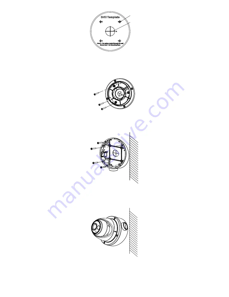
Screw Hole

Cable 

Hole


Figure 2-5


The Drill Template 

3.


Disassemble the inclined ceiling mount by the screw 

driver. 

4.


Install the turret camera’s mounting base on the 
inclined ceiling mount’s cover with three PM4 screws. 


Figure 2-6


Install


Turret


Camera’s Mounting Base


5.


Install the inclined ceiling mount’s body on the 
ceiling/wall with four PA4 

× 

25 screws, as shown in 

Figure 2-8. 


Figure 2-7


Fix the Inclined Ceiling Mount’s Body


6.


Combine the inclined ceiling mount’s cover with its 
body with supplied screws. 

7.


Repeat steps 5 to 8 of the 2.1 Ceiling/Wall Mounting 
without Junction Box
 to complete the installation. 


Figure 2-8


Fix the Camera to the Inclined Ceiling Mount 

2.3


Ceiling/Wall Mounting with Junction Box 

Before you start:   

You need to purchase a junction box separately. 
Steps: 
1.


Paste the drill template on the ceiling/wall. 

Summary of Contents for DS-2CE71D0T-PIRL

Page 1: ...ntact the dealer This manual applies to the models below Model DS 2CE71D0T PIRL This manual may contain technical incorrect places or printing errors and the content is subject to change without notice The updates will be added to the new version of this manual We will readily improve or update the products or procedures described in the manual 0200001080504 ...

Page 2: ...peration EU Conformity Statement This product and if applicable the supplied accessories too are marked with CE and comply therefore with the applicable harmonized European standards listed under the Low Voltage Directive 2014 35 EU the EMC Directive 2014 30 EU the RoHS Directive 2011 65 EU 2012 19 EU WEEE directive Products marked with this symbol cannot be disposed of as unsorted municipal waste...

Page 3: ... noise rise from the device turn off the power at once and unplug the power cord and then contact the service center Never attempt to disassemble the camera by unprofessional personal Cautions Do not drop the camera or subject it to physical shock Do not touch senor modules with fingers Do not place the camera in extremely hot cold the operating temperature shall be 40 C to 60 C dusty or damp loca...

Page 4: ... While in delivery the camera shall be packed in its original packing or packing of the same texture Mark Description Table 0 1 Mark Description Mark Description DC Voltage ...

Page 5: ... filter with auto switch OSD menu with configurable parameters Auto white balance Internal synchronization SMART IR mode Visible alarm PIR detection 3 axis adjustment 1 2 Overview DC12V IN Enclosure Main Body Mounting Base Power Cord 12 VDC Video Cable TVI White Light Source PIR Figure 1 1 Camera Overview ...

Page 6: ...e camera If the product does not function properly contact your dealer or the nearest service center Do NOT disassemble the camera for repair or maintenance by yourself 2 1 Ceiling Wall Mounting without Junction Box Steps 1 Disassemble the camera 1 Rotate the camera to align the notch to one of the marks 2 Pry the mounting base to remove the mounting base with the camera body with a flat object e ...

Page 7: ... check whether the image on the monitor is gotten from the optimum angle If not adjust the camera according to the figure below to get an optimum angle Rotation Position 0 to 360 Tilt Position 0 to 75 Pan Position 0 to 360 Figure 2 4 3 axis Adjustment 1 Hold the camera body and rotate the enclosure to adjust the pan position 0 to 360 2 Move the camera body up and down to adjust the tilt position 0...

Page 8: ...the ceiling wall with four PA4 25 screws as shown in Figure 2 8 Figure 2 7 Fix the Inclined Ceiling Mount s Body 6 Combine the inclined ceiling mount s cover with its body with supplied screws 7 Repeat steps 5 to 8 of the 2 1 Ceiling Wall Mounting without Junction Box to complete the installation Figure 2 8 Fix the Camera to the Inclined Ceiling Mount 2 3 Ceiling Wall Mounting with Junction Box Be...

Page 9: ...g base with those on junction box s cover 4 Fix the mounting base on junction box s cover by supplied screws Figure 2 10 Install Turret Camera s Mounting Base 5 Secure the junction box s body with supplied screws on the ceiling wall Figure 2 11 Install the Junction Box Camera Body on Ceilling Wall 6 Combine the junction box s cover with the junction box s body 7 Repeat steps 5 to 8 of 2 1 1 Ceilin...

Page 10: ... bracket with expansion screws on the wall 3 Secure the mount with four hex nuts and washers Wall Mount Figure 2 13 Install the Bracket 4 Install the mounting base of the turret camera to the wall mount and secure them with supplied screws Figure 2 14 Install the Mounting Base to the Bracket 5 Route the cables through the mount 6 Repeat steps 6 to 8 of 2 1 1 Ceiling Wall Mounting without Junction ...

Page 11: ...nnect the camera with the TVI DVR and the monitor shown as the figure 3 1 Camera TVI DVR Monitor Figure 3 1 Connection 2 Power on the analog camera TVI DVR and the monitor to view the image on the monitor 3 Click PTZ Control to enter the PTZ Control interface 4 Call the camera menu by clicking button or call the preset No 95 ...

Page 12: ... EXIT WHITE LIGHT SAVE EXIT DAY NIGHT BACK EXIT SAVE EXIT MODE IMAGE MODE Figure 3 2 Main Menu Overview 5 Click the direction arrow to control the camera 1 Click up down direction button to select the item 2 Click Iris to confirm the selection 3 Click left right direction button to adjust the value of the selected item 3 1 VIDEO FORMAT You can select the video format as 2MP 25fps or 2MP 30fps 3 2 ...

Page 13: ... be amplified when the AGC is on 3 4 DAY NIGHT COLOR B W Black White and AUTO are selectable for DAY and NIGHT switches Note Under the LIGHTING mode the image is colored all the time and there s no DAY NIGHT settings in the menu COLOR The image is colored in day mode all the time B W The image is black and white all the time and it is better to turn the IR LIGHT on in poor light conditions IR LIGH...

Page 14: ...OR GAIN 3 DNR and MIRROR are adjustable VIDEO SETTINGS IMAGE MODE WHITE BALANCE BRIGHTNESS CONTRAST SHARPNESS SATURATION DNR MIRROR BACK EXIT SAVE EXIT 5 5 5 5 5 O FF ST D Figure 3 4 VIDEO SETTINGS IMAGE MODE IMAGE MODE is used to adjust the image saturation and you can set it as STD Standard or HIGH SAT High Saturation WHITE BALANCE White balance the white rendition function of the camera is to a...

Page 15: ...tically HV The image flips 180 both horizontally and vertically 3 6 FUNCTIONS 3 6 1 WHITE LIGHT The embedded white light source can be worked as the visible alarm In the WHITE LIGHT mode you can set the mode as ALARM or OFF When you select the WHITE LIGHT as ALARM you can set the parameters in the TRIGGER MODE and the ALARM MODE to meet your needs TRIGGER MODE DVR Select the TRIGGER MODE as DVR In...

Page 16: ...eived and the rest can be done in the same way FLASHING Select the ALARM MODE as FLASHING In this way the white light source flashes when the PIR module received the alarm signal OFF Select OFF to give up this function 3 6 2 PIR LEVEL Adjust the sensitivity of the PIR module and the greater the value is the more sensitive the PIR module is 3 7 FACTORY DEFAULT Reset all the settings to the factory ...

Reviews: