


Control Panel User Manual
72
{4}
It indicates the value range of the day
(l)
.
Command Description Command Description Command Description
1
Monday
2
Tuesday
3
Wednesday
4
Thursday
5
Friday
6
Saturday
7
Sunday
{5}
Completing
Copy Weekly Schedule of Partition
To copy the settings of partition
(m)
to
partition
(n)
, please refer to the
command below.
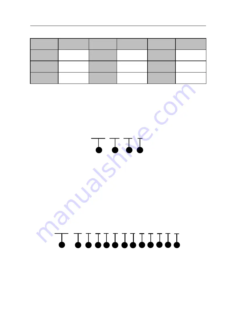
693 01 02 #
1
2
3
4
{1}
Copy Weekly Schedule of Partition Command Address: 693.
{2}
Partition
(m)
Number. 01~08 indicate partitions No.1~No.8.
{3}
Partition
(n)
Number. 01~08 indicate partitions No.1~No.8.
{4}
End the command.
Prior Schedule Date Parameter Configuration
To configure the date parameters of the prior schedule, please refer to the
command below.
694 00 0 0 0 0 0 0 0
0 0 0 #
1
2
4
6
3
5
8
7
9 10 11 12 13
{1}
Prior Schedule Date Parameter Configuration Command Address:
694.
{2}
It indicates the prior schedule number. 00~30 indicate prior
schedules No.00~No.30.
Summary of Contents for DS-19A08-F/Kx
Page 1: ...Control Panel User Manual 1 UD 6L0206D1044A02 Network Security Control Panel User Manual...
Page 13: ...Control Panel User Manual 13 Chapter 2 Installation and Wiring 2 1 Main Board Overview...
Page 100: ...Control Panel User Manual 100 2 Click to enter the interface of adding a network user...
Page 130: ...Control Panel User Manual 130...
Page 156: ...Control Panel User Manual 156...