background image

B-2

Factory-Installed Wheels

Technobeam

®

 User Manual

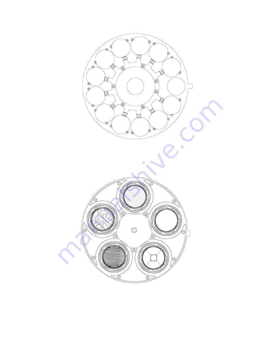
Technobeam color wheel:

Figure B-2.  Factory configuration of the Technobeam color wheel.

Technobeam rotating effects wheel:

Figure B-3.  Factory configuration of the Technobeam rotating effects wheel.

1

2

3

4

5

6

7

8

9

10

11

12

13

Pink

Aqua

Dark
Magenta

Green

Amber

Yellow

Dark
Blue

Red

Indigo

Orange

Light
Blue

CTO

Open

1 (open)

2

Prism

3

Lenticular

4

Slow

Glass

5

Frost

Summary of Contents for Technobeam

Page 1: ...fi User Manual High End Systems Inc 2217 West Braker Lane Austin TX 78758 USA 512 836 2242 www highend com p n 60600115 Version 2 0...

Page 2: ...ADDR...

Page 3: ......

Page 4: ...s Inc assumes no responsibility or liability for any errors or inaccuracies that may appear in this manual The system software for the Status Cue lighting console described in this manual is furnished...

Page 5: ...078 039 UK 2 043 769 US 5 331 822 US 5 402 326 US D 372550 UK 2292896 US D365165 US 5 430 629 US D360 404 US 5 455 748 0475082 US 5 506 762 M9604224 9 US 5 515 254 US D370080 UK 2 291 814 US 5 545 95...

Page 6: ...chnobeam Product Number All Product Options All conforms to the following EEC directives 73 23 EEC as amended by 93 68 EEC 89 336 EEC as amended by 92 31 EEC and 93 68 EEC Equipment referred to in thi...

Page 7: ...Anhang D Vor der Montage dem Zusammenbau und der Inbetriebnahme dieses Ger ts alle Anleitungen sorgf ltig durchlesen INFORMAZIONI IMPORTANTI DI SICUREZZA Le istruzioni sulla protezione da incendi folg...

Page 8: ...los Estados Unidos e internacionales Las modificaciones al producto podr an afectar la seguridad y dejar al producto fuera de conformidad con las normas de seguridad relevantes Warranty Information L...

Page 9: ...r freight can be sent customer collect in the Continental United States REPAIR OR REPLACEMENT AS PROVIDED FOR UNDER THIS WARRANTY IS THE EXCLUSIVE REMEDY OF THE CONSUMER HIGH END SYSTEMS INC MAKES NO...

Page 10: ...1 10 Setting the Beam Angle 1 12 Chapter 2 Setting Up Your Fixture Powering On the Fixture 2 2 Overview of Controller Operation 2 4 Linking the Fixtures to the Controller 2 7 Mounting the Fixture 2 8...

Page 11: ...Information A 1 Technobeam Protocol A 3 Technobeam i Protocol A 7 MSpeed Movement Times A 12 Macro Channel Assignments A 15 Fixture Number to DMX Start Channel A 16 Appendix B Factory Installed Wheels...

Page 12: ...s to a controller Make sure you terminate the last fixture in the link 2 8 Figure 2 7 Use a locking washer when attaching a fixture to a truss 2 10 Figure 2 8 Always use a safety cable when mounting t...

Page 13: ...ho effect and under the spring 6 10 Figure 6 11 When you replace a rotating litho or rotating effect make sure the tip of the spring is fully seated under the wheel tabs it cannot protrude from under...

Page 14: ...ables Table 1 1 Optional Accessories 1 5 Table 1 2 Beam Angles for Factory Installed 11 to 17 Degree Lens Set 1 14 Table 1 3 Beam Angles for Optional 8 to 12 Degree Narrow Angle Lens Set 1 14 Table 2...

Page 15: ...xii Technobeam User Manual...

Page 16: ...ng Up Your Fixture Powering On the Fixture 2 2 Overview of Controller Operation 2 4 Linking the Fixtures to the Controller 2 7 Mounting the Fixture 2 8 Configuring the Fixture 2 13 Upgrading Software...

Page 17: ...3 Technobeam i Protocol A 7 MSpeed Movement Times A 12 Macro Channel Assignments A 15 Fixture Number to DMX Start Channel A 16 Appendix B Factory Installed Wheels Technobeam Wheels B 1 Appendix C Imp...

Page 18: ...ys use a safety cable when mounting the fixture 2 11 Figure 2 9 Location of the T handle you use to adjust the yoke position 2 11 Figure 2 10 You can slide the yoke all the way back to allow the fixtu...

Page 19: ...moving the lamp assembly from the fixture 6 12 Figure 6 15 Pull straight up on the lamp grasping its ceramic base to remove it from the assembly 6 13 Figure 6 16 Hold the lamp by its ceramic base and...

Page 20: ...iii Ecodome User Manual 2...

Page 21: ...Ecodome User Manual iv...

Page 22: ...ng the DMX Start Channel 2 16 Table 2 3 Example Determining the Unique Fixture Number 2 17 Table 2 4 Example of Wasted DMX Channels 2 18 Table 3 1 Technobeam Menu Map 3 3 Table 6 1 Replacement Fuses 6...

Page 23: ...Ecodome User Manual ii...

Page 24: ...o 12 narrow angle lens set The fixture s remote focus provides razor sharp beam or image projection at various trim heights and throw distances As with all Lightwave Research intelligent luminaires Te...

Page 25: ...onstruction Lens tube wheel gears front and rear bezels manufactured from lightweight rugged engineering thermopolymer Tough powder coated aluminum side panels Molded handles for easy transportation l...

Page 26: ...jacent to Electrical Shock hazards Failure to heed these messages could result in injury to persons Appears adjacent to Explosion warnings Failure to heed these messages could result in injury to pers...

Page 27: ...8 voice 800 890 8989 24 hour FAX 512 834 9195 24 hour voice mail 512 837 3063 or 800 890 8989 West Coast High End Systems Inc 8200 Haskell Avenue Van Nuys CA 91406 voice 818 947 0550 FAX 818 908 8975...

Page 28: ...kerhedsinformation DANMARK 1 3 Dichroic Litho and Effects Specifications 1 4 Safety Standards 1 4 Electromagnetic Standards 1 4 Environmental Specifications 1 5 DMX Data Cabling 1 5 Controllers 1 5 Op...

Page 29: ...kg Electrical Specifications Voltages 100 120 230 V 50 Hz 3 75 3 13 1 6 A 100 120 208 V 60 Hz 3 75 3 13 1 8 A Rated power 375 W Power factor 120V 60 Hz 0 96 Power factor 230V 50 Hz 0 90 Fuses F1 125V...

Page 30: ...th blue neutral brown live This equipment must be earthed Vigtig Sikkerhedsinformation DANMARK Advarsel Beskyttelse mod elektrisk chock Vigtigt Lederen med gul groen isolation maa kun tilsluttes en kl...

Page 31: ...g specifications Dichroics Diameter 1 125 0 010 28 5 mm 0 25 mm Thickness 0 069 0 010 1 8 mm 0 25 mm Lithos Diameter image area 0 996 0 860 0 005 25 mm 22 mm 0 13 mm Maximum thickness rotating litho o...

Page 32: ...istance of 20 1000 ft nominal impedance 100 140 22 24 AWG with insulation having a dielectric rating of 300 volts or higher DMX data connectors 3 pin male and female XLR connectors DMX data terminator...

Page 33: ...t High End Systems Inc assumes no responsibility for products damaged during transport Therefore you should return a product for repair in its original shipping carton and packing materials Note Befor...

Page 34: ...the location in which you will use Technobeam different locations even within the same country might have different power cord cap requirements Note Because of the wide variety of power cord caps used...

Page 35: ...emme maerket Installing the Yoke You will need one 1 4 allen wrench This section explains how to install the moving track yoke You can adjust the yoke however you want to distribute the weight of the...

Page 36: ...If you want to reposition the yoke use a 1 4 allen wrench to loosen the allen screws on the side handles shown in Figure 1 1 on page 1 8 5 After loosening the side handle allen screws slide the yoke t...

Page 37: ...Blow Only WARNINGS 1 Check the voltage setting before proceeding with equipment setup 2 The information in this section is intended to assist qualified service personnel because this fixture is to be...

Page 38: ...and SW3 by the LED display as shown in Figure 1 4 Figure 1 4 The three voltage selection switches located next to the LED display 4 Choose a voltage frequency setting as shown in Figure 1 5 Figure 1 5...

Page 39: ...am angles are accurate to 1 1 Unplug the fixture and remove the access door shown in Figure 1 3 on page 1 11 if you have not done so already 2 Lay the fixture on its back and locate the lens tube as s...

Page 40: ...ted on the side of the lens The arrow printed on each lens must point toward the aperture i e away from the lamp 6 Lens positions in the lens tube are numbered from 1 to 10 both on the lens tube cover...

Page 41: ...the rear lenses must always be placed in slot 1 see Figure 1 8 on page 1 13 Table 1 3 Beam Angles for Optional 8 to 12 Degree Narrow Angle Lens Set Beam Angle Rear Lens Position Front Lens Position 8...

Page 42: ...m 2 9 Hanging the Fixture Straight Down 2 12 Configuring the Fixture 2 13 Fixture Types 2 13 Selecting a Control Method 2 14 DMX Start Channel Control Method 2 14 Fixture Number Control Method 2 14 As...

Page 43: ...Fixture Connect the fixture to an appropriately rated power outlet there is no power switch You will hear the sounds of the motors and gears as they home This is normal LED Display When the fixture ha...

Page 44: ...not be ON unless the fixture is connected to a DMX 512 link with a working controller If you have already connected Table 2 1 Status LEDs LED name State Problem Indication Description Motor solid red...

Page 45: ...a central location you need to connect the fixtures to a DMX 512 compatible controller using XLR data grade cabling What is DMX 512 Protocol DMX 512 is an industry standard protocol for controlling l...

Page 46: ...and a female 3 pin XLR connector on the other end Pin 1 is the common cable shield pin 2 is the data complement negative and pin 3 is the data true positive Figure 2 3 Properly constructed data cabli...

Page 47: ...bypass all controllers non High End Systems fixtures optoisolators and serial data distributors on the link if you want to perform software uploads or crossloads as described in the section titled Up...

Page 48: ...Out connector from one fixture to the Data In connector to the next fixture until you have linked all of the Technobeam fixtures 5 Connect other devices to the Technobeam fixtures as desired using the...

Page 49: ...end handles However you wish to mount the fixture you must follow the precautions and suggestions below Verify the input voltage you are using matches the fixture s voltage selection switches see the...

Page 50: ...3 If the surface is above floor height make sure you use safety cables as described in the next section Mounting the Fixture on a Truss or Other Support System If you are mounting the fixture on a tru...

Page 51: ...ld the fixture while it is being secured in place and one person to secure the fixture to its support and to attach clamps and safety cables 2 Always stand on a firm stable surface when mounting a fix...

Page 52: ...e see Figure 2 9 and orient the fixture to the desired tilt angle 7 Tighten the T handles to secure the fixture in the desired position 8 When you have the fixture in the position you want firmly tigh...

Page 53: ...lides backward 1 Use a 1 4 allen wrench to loosen the two yoke allen screws see Figure 2 10 2 Use a 1 4 allen wrench to loosen the four handle allen screws two on each handle 3 Slide the yoke to the r...

Page 54: ...Each fixture uses a fixture specific protocol which determines the number of DMX channels the fixture will use To change the fixture type see Setting the Fixture Type and Protocol TYPE on page 3 15 A...

Page 55: ...MX channels are wasted For more information see Wasted DMX Channels on page 2 17 To select the DMX start channel control method 1 Press and hold the Menu button until ADDR appears on the LED display 2...

Page 56: ...hat you want to respond independently to controller commands If you want two or more fixtures to respond to controller commands in exactly the same way all fixtures must be the same type for example t...

Page 57: ...t channel 1 you can determine the DMX start channel for each successive fixture by adding the number of DMX channels used by the fixture to the fixture s DMX start channel For example in Table 2 2 18...

Page 58: ...1 Press and hold the Menu button until ADDR appears on the LED display 2 Press the Enter button to enter the ADDR menu 3 Using the Up and Down arrow buttons scroll to the desired fixture number and pr...

Page 59: ...xture Number to DMX Start Channel on page A 16 which shows the channel ranges reserved for each Technobeam fixture type This table will help you determine the next available DMX start channel fixture...

Page 60: ...ms fixtures optoisolators or serial data distributors on the link These devices will prevent crossloading 2 If there are any Dataflash AF1000 xenon strobe fixtures Emulator laser simulators or Intella...

Page 61: ...tributor or High End Systems Customer Service in one of the ways shown in the section titled Contacting High End Systems on page Intro 4 WARNING This information is intended to assist qualified servic...

Page 62: ...ge 2 25 2 Cause Fan has failed Solution Home the fixture either by unplugging the fixture and plugging it back in or by selecting HOME from the Test menu Put your hand over the exhaust vent shown in F...

Page 63: ...he section titled Replacing Fuses on page 6 2 to inspect the fuses and replace them if necessary Dim flags close fixture does not respond to control commands lamp shuts off fan turns off Possible caus...

Page 64: ...ion Visually inspect the hot mirror for cracks or deep scratches as shown in the section titled Cleaning the Lenses and Mirrors on page 6 16 3 Cause Fan has failed Solution Home the fixture either by...

Page 65: ...uses and solutions 1 Cause Incorrect lens installation Solution Make sure you have installed the lenses in the correct orientation as shown in the section titled Setting the Beam Angle on page 1 12 2...

Page 66: ...the documentation provided with the controller for more information 6 Verify the DMX data for other fixtures on the link see Viewing DMX Status and Construct Values FIXT on page 3 24 or Viewing DMX D...

Page 67: ...invert status S DN shutdown time SWAP pan tilt swap status TIMB time base seconds minutes hours for preset playback The most likely cause is that an electrical event occurred and either interrupted d...

Page 68: ...tures after all Technobeam fixtures is a good way to do this After removing the offending device s from the data link attempt the crossload again Link Empty Occurs when the crossloading fixture fails...

Page 69: ...oltage on page 1 10 If the voltage setting is correct contact High End Systems Customer Service in one of the ways shown in the section titled Contacting High End Systems on page Intro 4 PRST Lost Pre...

Page 70: ...ure Software XLD 3 19 Test Menu TEST 3 20 Homing the Fixture HOME 3 20 Turning the Lamp On or Off LAMP 3 20 Copying the Boot Code BOOT 3 21 Performing Self Tests SELF 3 21 Placing the Fixture in Setup...

Page 71: ...button Note If you do not press the Enter button the new option you selected will not be stored Pressing the Menu button returns you to the previous option or menu without changing the value of an op...

Page 72: ...xxx change the existing fixture number DMX start channel SET FACT ON set factory defaults on OFF set factory defaults off Note Selecting this option has no affect on individual preset values SWAP ON s...

Page 73: ...extinguish the lamp L ON strike the lamp BOOT copy the boot sector SELF ALL self test all constructs PAN self test mirror pan movement TILT self test mirror tilt movement COL self test color wheel mo...

Page 74: ...e DMX MSpeed time value LAD view the DMX Laser Aiming Device LAD value CNTL view the DMX control channel value DATA C001 C512 view the DMX data for the selected DMX channel Note You can only view DMX...

Page 75: ...ast scanning full speed RND color wheel random color positions full speed BLK color wheel blink selection full speed MIDX color wheel indexed position MSpeed MFSP color wheel forward spin MSpeed MRSP...

Page 76: ...selected a COLC construct value of BLK or MBLK HB 1 HB13 shutter blink on selected half color position only available if you selected a COLC construct value of BLK or MBLK LTOC IDX litho wheel indexed...

Page 77: ...nly available if you selected a LTOC construct value of RSP or MRSP S000 S255 select a litho scan speed from slow S000 to fast S255 only available if you selected a LTOC construct value of SC or MSC N...

Page 78: ...in decimal seconds from fast 0 15 to slow 252 7 XFAD X 0 1 X 9 9 select the DIM and FCUS construct s crossfade time in increments of 0 1 X 10 X166 select the DIM and FCUS construct s crossfade time i...

Page 79: ...s to select a new DMX start channel C001 C512 fixture number F 01 F xx The LED display will flash when a new option is selected 4 Press the Enter button to accept the new fixture number DMX start chan...

Page 80: ...heir factory defaults settings 5 Press and hold the Menu button until ADDR appears on the LED display 6 Using the Up and Down arrow buttons scroll to the SET menu and press the Enter button to select...

Page 81: ...wn arrow buttons scroll to the SET menu and press the Enter button to select the SET menu 3 Using the Up and Down arrow buttons scroll to the T IN menu and press the Enter button to select the T IN me...

Page 82: ...haracters D IN This menu item allows you to invert the orientation of the LED display s alphanumeric characters This option is useful if your fixture is standing upright i e resting on its bottom pane...

Page 83: ...th this option enabled after the current lamp hours exceed 2 200 hours the fixture will display the warning message LAMP OUT ERR Once the lamp is extinguished the fixture will no longer strike the lam...

Page 84: ...n the link The procedures below are listed in the order that they appear on the menu map Setting the Fixture Type and Protocol TYPE Use this menu item to change the fixture type and protocol The proto...

Page 85: ...uses 18 DMX channels and allows you to access the macros To set the fixture type and protocol 1 Press and hold the Menu button until ADDR appears on the LED display 2 Using the Up and Down arrow butto...

Page 86: ...g the Up and Down arrow buttons choose the A option to select user A settings or the B option to select user B settings Press the Enter button to select the desired option Copying User Presets PRST Us...

Page 87: ...uttons scroll to the COPY menu and press the Enter button to select the COPY menu 5 Using the Up and Down arrow buttons scroll to the SETT menu and press the Enter button to select the SETT menu 6 Usi...

Page 88: ...es on the link 2 On the crossloading fixture only press and hold the Menu button until ADDR appears on the LED display 3 Using the Up and Down arrow buttons scroll to the MODE menu and press the Enter...

Page 89: ...8 see Table 1 on page A 3 or Table 2 on page A 8 To manually home the fixture 1 Press and hold the Menu button until ADDR appears on the LED display 2 Using the Up and Down arrow buttons scroll to the...

Page 90: ...tore the new boot code then automatically home Performing Self Tests SELF This menu item performs the appropriate self tests for the following ALL performs all of the self tests listed below PAN moves...

Page 91: ...button to select the S UP option 4 When the LED displays SET NOW mechanically home the fixture 5 After mechanically homing the fixture press any button This causes the fixture to electronically home T...

Page 92: ...ay OVER TEMP Viewing the Current Lamp Hours L HR To view the number of hours the lamp has been on since this option was reset 1 Press and hold the Menu button until ADDR appears on the LED display 2 U...

Page 93: ...Down arrow buttons scroll to the INFO menu and press the Enter button to select the INFO menu 3 Using the Up and Down arrow buttons scroll to the VER option and press the Enter button to select the V...

Page 94: ...o the INFO menu and press the Enter button to select the INFO menu 3 Using the Up and Down arrow buttons scroll to the DMX menu and press the Enter button to select the DMX menu 4 Using the Up and Dow...

Page 95: ...on to select the DMX menu 4 Using the Up and Down arrow buttons scroll to the DATA menu and press the Enter button to select the DATA menu 5 Using the Up and Down arrow buttons scroll to the desired D...

Page 96: ...d Down arrow buttons scroll to the desired option listed above and press the Enter button to select the desired option to view its sensor information Resetting Fixture Hours F RS This menu item allows...

Page 97: ...ne within the fixture s on board memory capture a scene from your DMX controller to the fixture s on board memory and enable the fixture s factory programmed preset sequence self demo Setting Preset P...

Page 98: ...he LED display 2 Using the Up and Down arrow buttons scroll to the PRST menu and press the Enter button to select the PRST menu 3 Using the Up and Down arrow buttons scroll to the COPY menu and press...

Page 99: ...l appear briefly in the fixture s LED display Note You must use the fixture s on board scene memory to manually select values for the XFAD DLAY and TIME constructs since a DMX controller will not tran...

Page 100: ...ts and Values 4 4 Creating a Scene 4 4 Orienting and Powering On the Fixture 4 4 Turning on the Lamp 4 4 Opening the Shutter 4 5 Positioning the Mirror 4 6 Focusing on a Litho 4 6 Selecting Color Whee...

Page 101: ...cenes contiguously in other words scene 1 scene 2 scene 3 scene 4 and so on without skipping a scene because the fixture automatically repeats when it encounters the first unprogrammed scene or when a...

Page 102: ...s you need to keep in mind while you are creating and playing back scenes on the fixture Subject to Change The information in the following sections is based on what was available at the time this man...

Page 103: ...o the light will be projected onto a flat light colored object such as a white wall or ceiling If you have Technobeam you will be able to move the mirror to a suitable position 2 Follow the instructio...

Page 104: ...t because each fixture is slightly different 5 Press Enter to begin creating scene 1 6 If you can see light exiting the fixture the shutter is already open skip to the next section 7 Use the Up and Do...

Page 105: ...r Focusing on a Litho 1 Use the Up and Down arrow keys to navigate to the LTOC control construct 2 Press Enter then use the Up and Down arrow keys to select IDX 3 Press Enter to accept your selection...

Page 106: ...ocusing the Fixture If you selected the suggested constructs you should now see a litho pattern being changed by a rotating effect and random color changes This section shows how you can use the fixtu...

Page 107: ...he current scene number F001 indicates you will copy from scene 1 5 Press Enter to select scene 1 to copy from The display then shows TO 6 Press Enter the LED display shows the previously selected sce...

Page 108: ...should look similar to the one below Figure 4 2 A dot always appears in the LED display whenever preset playback is on 5 To turn preset playback off keep pressing the Menu key to select the PLAY optio...

Page 109: ...link Note After you enable preset playback on the fixture you configured as fixture 1 or DMX start channel 1 the Transmit LED on that fixture will continue flickering yellow until you disable preset p...

Page 110: ...you are already familiar with your controller if not consult the controller s documentation It also assumes you have some familiarity with using the menu system on Technobeam if not review Chapter 3 a...

Page 111: ...the XFAD and DLAY constructs since the controller does not transmit those constructs Note If the scene you captured to was previously programmed you will need to make that scene active in order to vie...

Page 112: ...dience 5 3 Using the Laser Aiming Device 5 3 Controlling the Laser 5 5 Menu Control of the Laser 5 5 DMX Control of the Laser 5 5 Troubleshooting 5 6 Laser gradually loses power 5 6 Laser is out of po...

Page 113: ...pment 6 When not in use the laser fixture should be stored in a location where unauthorized personnel cannot gain access 7 Do not remove the labels shown at the bottom of this page they are required b...

Page 114: ...s bright the laser will be If the fixture operates with the lamp on at 40 C 104 F for example laser power will be decreased by about 25 Technobeam was designed so the laser light can exit the fixture...

Page 115: ...nd light beam In its ideal position the laser path is parallel to the path of the light and will stay 2 5 cm above the center point of the beam at any throw distance or mirror position If the laser be...

Page 116: ...ons controlling the laser aiming device with the MACR construct is shown below LROF laser aiming device OFF LRON laser aiming device ON continuously LM01 to LM30 laser modulation levels LM01 is slow m...

Page 117: ...If this is happening contact High End Systems Customer Service in one of the ways shown in Contacting High End Systems on page Intro 4 Laser is out of position Align the laser as shown in the section...

Page 118: ...e in and make sure you have enabled the laser as shown in the section titled Controlling the Laser on page 5 5 5 If the Emission Indicator LED and laser are both still OFF contact High End Systems Cus...

Page 119: ...ntacting High End Systems on page Intro 4 Laser ON Emission Indicator LED OFF The most likely reason is a faulty Emission Indicator LED Contact High End Systems Customer Service as shown in Contacting...

Page 120: ...t 6 7 Removing a Static Litho 6 8 Cleaning the Litho 6 8 Litho Installation Instructions 6 9 Replacing a Static Litho 6 9 Replacing a Rotating Litho or Effect 6 10 Replacing a Custom Litho 6 11 Replac...

Page 121: ...r before re lamping or servicing 4 Replace fuses with the specified type and rating only 5 Never look directly at the lamp while lamp is on 6 The procedures in this chapter are intended to assist qual...

Page 122: ...election switches and fuses as well as wheels and optics 3 Note which fuse s needs to be replaced and make sure you replace it with a fuse of the same type and rating as shown in Table 6 2 Table 6 2 F...

Page 123: ...he edge or uncoated side of the glass when removing or installing lithos If possible wear cloth gloves when inserting and removing lithos from the litho wheel housing If necessary clean the lithos wit...

Page 124: ...hows the location of each wheel in the Technobeam fixture Figure 6 3 Location of the wheels in Technobeam Replacing Dichroics in the Color Wheel This section shows how to change individual dichroic fi...

Page 125: ...a soft lint free cotton cloth 5 Carefully install the replacement dichroic oriented so the coated side is facing toward the lamp and the uncoated glass side is facing toward the rotating litho wheel T...

Page 126: ...r in their respective wheels to clean them or to add new ones See the section titled Optional Accessories on page 1 5 for ordering information Removing a Rotating Litho or Rotating Effect 1 Rotate the...

Page 127: ...o 1 Rotate the wheel until the desired litho is easy to access 2 Carefully spread the wheel apart and reach behind the wheel to remove the litho as shown Figure 6 7 Figure 6 7 To replace a static lith...

Page 128: ...o 1 Carefully handling the litho by its edges only separate the wheel and drop the litho into the retaining slot and between the two retaining tabs as shown in Figure 6 8 Figure 6 8 Location of the re...

Page 129: ...must be placed on top of the litho effect and under the spring 3 Carefully replace the spring turning it as you compress it until the spring is fully seated in the litho holder Make sure the spring f...

Page 130: ...lamp in your fixture not the MSD 250 Technobeam fixtures are optimized for the MSD 250 2 lamp and will give reduced performance with other lamps WARNINGS 1 This equipment is designed for use with an M...

Page 131: ...7 Disconnect power before re lamping or servicing 1 Unplug the fixture from the power source 2 Fully back out the two lamp assembly screws shown in Figure 6 13 Figure 6 13 Loosening the lamp assembly...

Page 132: ...16 Do not force the lamp into the socket doing so could break the lamp Figure 6 16 Hold the lamp by its ceramic base and gently press the two base pins into the socket Caution Avoid touching any part...

Page 133: ...anywhere other than the center of the light beam The optimization procedure below describes how to optimize the lamp using the fixture s onboard menu system However you can access the same options usi...

Page 134: ...m or the hot spot of brightness is at the center of the beam retighten the two optimization screws to secure the lamp in its new position Resetting Lamp Hours After changing a lamp you should reset th...

Page 135: ...oor is removed use a soft lint free cotton cloth and warm soapy water if necessary to clean dust and dirt from the inside and outside of the vents shown in Figure 6 19 Cleaning the Lenses and Mirrors...

Page 136: ...sed carefully use your fingers to open them to clean the inside of the glass 4 Locate the lens tube as shown in Figure 6 21 Figure 6 21 The lens tube contains the zoom lenses 5 Carefully lift the cove...

Page 137: ...Inspect the hot mirror shown in Figure 6 22 for cracks deep scratches or other damage If you notice significant damage High End Systems Customer Service in one of the ways shown in the section titled...

Page 138: ...igure 6 23 shows the ideal position of the laser from the center of a perfectly round light beam Figure 6 23 The ideal position of the laser is no more than 2 5 cm directly above the center of a perfe...

Page 139: ...eye level The section titled Safety Precautions on page 5 2 has a complete listing of safety precautions for using the Laser Aiming Device Live Components You will be accessing live components and ad...

Page 140: ...n 10 ft 3 m away 3 Connect the fixture to an appropriately rated power outlet You will hear sounds as wheels and motors seek their home positions this is normal 4 When the fixture has finished homing...

Page 141: ...of time you selected a programmed scene The next two steps show how to unprogram a scene you need to unprogram the scene in order to make sure all constructs are set to default values This is necessar...

Page 142: ...n use the Up and Down arrow keys to adjust the mirror position 29 Press Enter to accept your selection for PAN 30 Continue adjusting the mirror using PAN and TILT until the beam is as round as possibl...

Page 143: ...select a value of OFF 40 Press Enter The lamp now shuts off 41 Keep pressing the Menu key until the ADDR option is displayed 42 Use the Up and Down arrow keys to navigate to the PRST menu 43 Use the U...

Page 144: ...izontally and screw 2 moves the laser vertically Use the three alignment screws to adjust the position of the laser so that it is no more than 2 5 cm directly above the center point of the beam shown...

Page 145: ...6 26 Technobeam Laser Aiming Device Technobeam User Manual...

Page 146: ...hoose the reduced protocol which gives you 8 bit control over mirror and litho positioning The full protocols give you two channels of position control one channel sets the most significant 8 bits coa...

Page 147: ...e crossfade or delay time Make sure your MSpeed value is at least as long as the crossfade or delay time otherwise the color or litho change will not complete before the next page or scene starts MSpe...

Page 148: ...s to center of aperture 0 15 0 5 00h 0Fh Forward spin 16 31 6 12 10h 1Fh Reverse spin 32 47 13 18 20h 2Fh Continuous 48 63 19 24 30h 3Fh Slow scan 64 79 25 30 40h 4Fh Fast scan 80 95 31 37 50h 5Fh Ran...

Page 149: ...9 75 78 C0h C7h Half color 9 and 10 200 207 79 81 C8h CFh Half color 10 and 11 208 215 82 84 D0h D7h Half color 11 and 12 216 223 85 87 D8h DFh Half color 12 and 13 224 231 88 90 E0h E7h Half color 13...

Page 150: ...Then use chs 8 9 10 F or chs 6 7 R to set other options Random and scan pause time set by ch 9 F or ch 7 R Indexed wheel snaps to center of aperture 128 143 50 56 80h 8Fh Forward spin 144 159 57 62 9...

Page 151: ...Speed use ch 16 F or 13 R to set MSpeed time Select the position with this channel Then use ch 12 F or ch 9 R to set spin direction and speed Position 1 128 153 50 60 80h 99h Position 2 154 178 61 69...

Page 152: ...u power up the fixture on a link when there is a controller present and it is sending data commands Technobeam i Protocol Table 2 lists the 18 Technobeam i constructs and their corresponding DMX contr...

Page 153: ...exed 128 143 51 56 80 8F Forward Spin 144 159 57 62 90 9F Reverse Spin 160 175 63 69 A0 AF Continuous 176 191 70 75 B0 BF Slow Scan 192 207 76 81 C0 CF Fast Scan 208 223 82 88 D0 DF Random 224 239 89...

Page 154: ...1 196 77 C4 Color 12 215 84 D7 Color 13 235 92 EB Color 1 open 255 100 FF Scan Mode two colors Color 1 and 2 0 23 0 8 00 17 Color 2 and 3 24 31 9 12 18 1F Color 3 and 4 32 39 13 15 20 27 Color 4 and 5...

Page 155: ...everse Spin 160 175 63 69 A0 AF Scanning 176 191 70 75 B0 BF Blink 192 207 76 81 C0 CF Random 208 223 82 88 D0 DF Reserved for Future Use 224 239 89 94 E0 EF Wheel Spin 240 255 95 100 F0 FF 8 Litho Wh...

Page 156: ...CD E5 Effect 5 230 255 91 100 E6 FF 12 Effects Rotate Rotate Clockwise Fastest 0 0 00 Rotate Clockwise Slowest 120 47 78 No rotation 121 134 48 52 79 86 Rotate Counter Clockwise Slowest 135 53 87 Rota...

Page 157: ...2 23 38 3B Macro 14 60 63 24 25 3C 3F Macro 15 64 67 25 26 40 43 Macro 16 68 71 27 28 44 47 Macro 17 72 75 28 29 48 4B Macro 18 76 79 30 31 4C 4F Macro 19 80 83 31 33 50 53 Macro 20 84 87 32 34 54 57...

Page 158: ...EDh 15 56 193 76 C1h 45 19 149 58 95h 1 60 236 93 ECh 16 06 192 75 C0h 46 04 148 58 94h 1 75 235 92 EBh 16 57 191 75 BFh 46 90 147 58 93h 1 92 234 92 EAh 17 09 190 75 BEh 47 77 146 57 92h 2 09 233 91...

Page 159: ...14 59 23 3Bh 232 96 14 5 0Eh 92 76 103 40 67h 155 71 58 23 3Ah 234 90 13 5 0Dh 93 98 102 40 66h 157 30 57 22 39h 236 84 12 5 0Ch 95 21 101 40 65h 158 89 56 22 38h 238 79 11 4 0Bh 96 45 100 39 64h 160...

Page 160: ...Value Value hex off 0 7 120 255 0 3 47 100 00h 07h 78h FFh 1 8 11 4 08h 0Bh 2 12 15 5 0Ch 0Fh 3 16 19 6 7 10h 13h 4 20 23 8 9 14h 17h 5 24 27 10 18h 1Bh 6 28 31 11 12 1Ch 1Fh 7 32 35 13 20h 23h 8 36 3...

Page 161: ...distributor to regenerate and retime the signal Table A 5 Fixture Number to DMX Start Channel Conversion Fixture Number DMX Start Channel 18 ch TB F TB I DMX Start Channel 14 ch TB R 1 1 1 2 19 15 3 3...

Page 162: ...e of the wheels are the position numbers used by a controller to select that effect For example choosing position 6 on the Technobeam rotating litho wheel see Figure B 1 with a controller selects the...

Page 163: ...of the Technobeam color wheel Technobeam rotating effects wheel Figure B 3 Factory configuration of the Technobeam rotating effects wheel 1 2 3 4 5 6 7 8 9 10 11 12 13 Pink Aqua Dark Magenta Green Am...

Page 164: ...plug attach the appropriate line cord plug according to the following code brown live blue neutral green yellow earth 2 As the colours of the cores in the mains lead of this equipment may not correspo...

Page 165: ...n permanente contre les incendies 1 Cet appareil est con u uniquement pour une lampe m tallique halog ne Philips s rie M de 250 watts base GY9 5 Son utilisation avec tout autre type de lampe peut tre...

Page 166: ...Changer la lampe si elle est endommag e ou thermiquement d form e Anhang C Wichtige Hinweise F r Ihre Sicherheit WARNUNG ZUM SCHUTZ VOR BRANDGEFAHR 1 Dieses Ger t ist nur f r den Gebrauch mit einer 25...

Page 167: ...bschalten der Netzspannung sollten Sie etwa 5 Minuten warten bevor Sie das Lampengeh use ffnen Sch tzen Sie beim Auswechseln der Lampen Ihre H nde und tragen Sie eine Schutzbrille 3 Die Oberfl chen de...

Page 168: ...ndi Mai guardare direttamente verso la lampadina quando sia accesa AVVERTENZA PER NON FERIRE AD ALTRE PERSONE 1 Al montare questa apparechiatura usare un secondo cavo di sicurezza 2 Avvertenza la lamp...

Page 169: ...ompleta de la l mpara o bien si el blindaje los lentes o las pantallas ultravioletas est n da adas 2 Cambie el blindaje los lentes o las pantallas ultravioleta si nota una aver a visible a tal grado q...

Page 170: ...Aiming Device 5 5 Crossload 3 19 Crossloading 2 19 Custom lithos 6 11 Customer Service intro 4 D Dichroics coated side 6 6 replacing 6 5 to 6 7 Dimensions 1 2 Display 2 13 DMX 512 cabling 2 4 cabling...

Page 171: ...ng fuses 6 2 to 6 4 safety standards 1 4 setting beam angle 1 12 to 1 14 setting voltage 1 10 1 11 specifications 1 2 to 1 5 troubleshooting 2 20 to 2 24 uploading 2 18 2 20 wheels B 1 B 2 yoke 2 12 i...

Page 172: ...2 A 1 A 15 Menu key 3 2 Menu system accessing 3 2 Mode menu MODE 3 15 Model numbers 1 2 Motor LED 2 3 2 4 Mounting fixture 2 8 to 2 11 MSpeed change 4 3 MSpeed movement times A 12 to A 14 N Narrow ang...

Page 173: ...umbers 1 2 safety 1 4 weight 1 2 Static litho 6 8 6 9 Synchronizing preset playback 4 9 T Technical Support intro 4 Terminator 2 5 Terminators 2 5 Test menu TEST 3 20 Tilt inverting T IN 3 12 swapping...

Reviews: