HF-A11 Embedded WiFi Module User Manual
Shanghai High-Flying Electronics Technology Co., Ltd
www.hi-flying.com
53
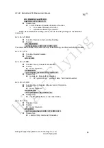
Network Protocal:TCP/Server, Port ID: 8899;
-- See “Application Setting Page”
LAN IP address: 10.10.99.254 (Different net segment with WAN port);
--See “AP Interface Setting
Page”
Module 3# Setting:
Works as STA mode; --See “Mode Selection Page”
WAN connection type: Static IP: 10.10.100.101;
--See “STA Interface Setting
Page”
Network Protocal:TCP/Client, Port ID: 8899; Application IP address: Module 2#’s
WAN IP address (10.10.100.100);
-- See “Application Setting Page”
LAN IP address: 10.10.98.254 (Different net segment with WAN port);
--See “AP Interface Setting Page”
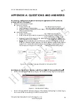
Figure 49. Two HF-A11 Modules Connection Through AP
Q6: How to avoid IP address confliction when apply HF-A11 module?
¾
The following address allocation method can avoid the IP address confliction for dynamic
and static IP address mixed application.
Module dynamic IP address range from 100 to 200 for last IP address segment.
Such as default IP: 10.10.100.254. When module works as AP, the IP address
module can allocate to STA is from 10.10.100.100 to 10.10.100.200;
So, if user needs to set static IP for dedicated STA internal network, the available IP
address range can start from 10.10.100.1 to 10.10.100.99.
Q7: PC works as server, all HF-A11 modules works as data acquisition card
and connect with PC, how to configure this application?
¾
Network structure as below figure: Three HF-A11 module setup 3 TCP links with PC server.
Module 1# works as AP and all devices connect to module 1# through WiFi interface;
PC
Setting:
IP address: 10.10.100.100;
Network Protocal:TCP/Server, Port ID: 8899;
Module 1# Setting:
Works as AP mode;
LAN IP address: 10.10.100.254;
High-Flying

