background image

HF-A11 Embedded WiFi Module User Manual 

Shanghai High-Flying Electronics Technology Co., Ltd 

www.hi-flying.com 

32


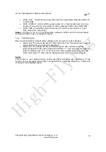
Figure 33.   “TCPUDPDbg” Tools Connection 

Now, in transparent transmission mode (HF-A11 default setting), data can be transferred from 
“CommTools” program to “TCPUDPDbg” program, or in reverse. You can see data in receiver 
side will keep same as in sender side. 

3.3. Typical Application Examples 

3.3.1. Wireless 

Control 

Application 


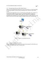
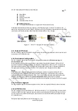
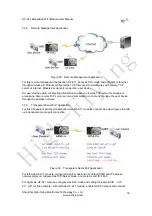
Figure 34.  Wireless Control Application 

For this wireless control application, HF-A11 works as AP mode. Module’s serial port connects to 
user device. So, control agent (Smart phone for this example) can manage and control the user 
device through the wireless connection with HF-A11 module. 

High-Flying

Summary of Contents for HF-A11

Page 1: ...PIO Ethernet Data Interface Support Work As STA AP AP STA Mode Support Router Bridge Mode Networking Support Internal External Antenna Option Support Max TCP links 32 Support AT Instruction Set for Co...

Page 2: ...Link Connection 17 1 4 4 TCPB Function 17 1 4 5 GPIO Function 17 1 4 6 Palmodic Signal 18 2 FUNCTIONAL DESCRIPTION 19 2 1 Wireless Networking 19 2 1 1 Basic Wireless Network Based On AP Infrastructur...

Page 3: ...NSTRUCTION INTRODUCTION 35 4 1 Configuration Mode 35 4 1 1 Switch to Configuration Mode 35 4 2 AT Instruction Set Overview 36 4 2 1 Instruction Syntax Format 36 4 2 2 AT Instruction Set 37 4 2 2 1 AT...

Page 4: ...e LAN IP and WAN IP through Web Page 50 Q3 How to configure transparent serial port application UDP protocol with two HF A11 modules 51 Q4 Where to set HF A11 module network protocol TCP UDP 51 Q5 How...

Page 5: ...ace Networking As STA Z Ver 24 Figure 21 HF A11 Transparent Transmission Demo 25 Figure 22 Open Web Management page 26 Figure 23 Mode Selection Page 27 Figure 24 AP Interface Setting Page 27 Figure 25...

Page 6: ...Kit Interface Description 12 Table 5 HF A11 Web Access Default Setting 26 Table 6 Error Code DescribtionHF A11 Web Access Default Setting 37 Table 7 AT Instruction Set List 37 HISTORY Ed V3 1 Created...

Page 7: ...tenna Option Internal On board chip antenna UART 1200bps 230400bps GPIOs Data Interface Ethernet 100Mpbs Operating Voltage 3 3V 5 Operating Current 170mA 300mA Operating Temperature 40 85 Storage Temp...

Page 8: ...wer 3 3V 350mA power input UART Data Transmit UART_TXD O 3 GPIO GPIO3 I O UART Data Receive UART_RXD I 4 GPIO GPIO4 I O UART sends request of data transmission UART_RTS O 5 GPIO GPIO5 I O UART receive...

Page 9: ...oot up process 1 Module boot up not finish Can be configured as GPIO Restore configuration nReload I 10 GPIO GPIO10 I O Module will Restore factory default configuration after set this pin 0 more than...

Page 10: ...ll cover include plastic shall away from antenna at least 10mm Figure 4 HF A11 Chip Antenna Keep Out Region High Flying suggest HF A11 module better locate in following region at customer board which...

Page 11: ...etailed application The evaluation kit shown as below user can connect to HF A11 module with the RS 232 UART port 100M Eth port or Wireless port to configure the parameters manage the module or do the...

Page 12: ...d application Figure 7 HF A11 Order Information Function Name Description DC jack 5 18V power input connector 3 Pin 3 Pin RS485 interface DB9 Male serial jack of 9 pin and used to connect to PC RJ 45...

Page 13: ...hm pull up resister internal When module connect to AP STA mode or some WiFi STA connect to module AP mode the module will output 0 This signal used to judge if module already at WiFi connection statu...

Page 14: ...t PHY to PHY connection will use AC coupled connection This is a space and cost optimized solution Hardware reference design as following Note VCC signal at reference design shall base on user board P...

Page 15: ...down resister user can t add pull up pull down resister on user board which may cause module can t work 1 3 4 Power Interface HF A11 module support single 3 3V power supply The peak current shall abo...

Page 16: ...e of users original serial devices is directly replaced with the module user devices can be easy for wireless data transmission without any changes The transparent transmission mode can fully compatib...

Page 17: ...Web configuration supported The command as following AT TCPB on Enable TCPB function AT TCPPTB port Set TCPB port number AT TCPADDB IP or domain Set TCPB s server address AT TCPTOB time Set TCPB timeo...

Page 18: ...ignal Base on selected factory default setting nReady signal can have two output statuses Status One The module will output 0 after normal boot up This signal used to judge if module finish boot up an...

Page 19: ...HF A11 Functional Architecture Notes AP that is the wireless Access Point the founder of a wireless network and the centre of the network nodes The wireless router we use at home or in office may be...

Page 20: ...as an AP and HF A11 2 HF A11 3 and the laptop are STAs connected to HF A11 1 Meanwhile all HF A11 modules can connected to user device via UART interface All HF A11 modules can be operated and manage...

Page 21: ...configure module works as STA mode it s AP interface still active AP STA Mode Notes When user enable AP STA function the STA port need to keep connected with other router AP or STA port will have to...

Page 22: ...support UART auto frame function If user select open this function and setting auto frame trigger length and auto frame trigger time parameters then module will auto framing the data which received fr...

Page 23: ...net Interface Networking As AP Figure 18 HF A11 Ethernet Interface Networking As AP For above networking HF A11 module works as AP and also the centre of this network All devices IP address in this ne...

Page 24: ...nd a AP to associated 2 8 Work Mode HF A11 modules provide two kinds of work mode Transparent transmission mode and Agreement Transmission mode Transparent transmission mode achieves a plug and play s...

Page 25: ...ss network parameters configuration is done on a PC connected to the same wireless network AT instruction set configuration means user configure parameters through serial interface command Refer to AT...

Page 26: ...3 Then input user name and password in the page as following and click OK button Figure 22 Open Web Management page The HF A11 web management page support English and Chinese language User can select...

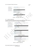
Page 27: ...e Setting Page This page use to setting the parameters when HF A11 module works as AP Figure 24 AP Interface Setting Page 3 1 4 STA Interface Setting Page This page use to setting the parameters when...

Page 28: ...ng com 28 Figure 25 STA Interface Setting Page 3 1 5 Application Setting Page This page use to setting the parameters of serial port communication such as UART setting and high layer network protocol...

Page 29: ...e general setting such as administrator setting restart module button restore factory default setting button and update firmware through webpage Figure 27 Device Management Page Notes Restart module b...

Page 30: ...other PC1 or user device connect to HF A11 module with serial port Figure 28 STA Interface Debug Connection Use HF A11 AP interface Debug PC2 connect to HF A11 through wireless connection another PC1...

Page 31: ...onnection If HF A11 configured as Server mode TCPUDPDbg Tools shall create Client mode connection Or otherwise create a Server mode connection Figure 31 TCPUDPDbg Tools Create Connection Then setting...

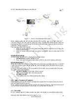
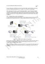
Page 32: ...PDbg program or in reverse You can see data in receiver side will keep same as in sender side 3 3 Typical Application Examples 3 3 1 Wireless Control Application Figure 34 Wireless Control Application...

Page 33: ...or storage or processing Also remote TCP server can send command to control and manage the user device through the wireless network 3 3 3 Transparent Serial Port Application For this transparent seria...

Page 34: ...te each other and think the connection between them is fully transparent 3 3 4 Wireless Data Acquisition Card Application For this wireless data acquisition card application one PC works as data serve...

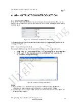
Page 35: ...truction set which cover all web page setting function 4 1 1 Switch to Configuration Mode Two steps to finish switching from transparent transmission mode to configuration mode UART input after module...

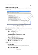
Page 36: ...mand style the description of syntax format as follow Format Description Means the parts must be included Means the optional part Command Message AT CMD op para 1 para 2 para 3 para 4 CR AT Prefix of...

Page 37: ...n Close UART auto frame function UARTFT Set Query UART auto frame trigger time UARTFL Set Query UART auto frame trigger length TMODE Set Query data transmition mode transparent transmition or agreemen...

Page 38: ...ersion information H Help Notes HF A11 module can works as AP or STA user have to use different AT Instruction to set WiFi parameters when module works as AP or STA mode 4 2 2 1 AT E Function Open Clo...

Page 39: ...UART baudrate data_bits stop_bit parity CR ok CR LF CR LF Parameters baudrate 1200 1800 2400 4800 9600 19200 38400 57600 115200 230400 345600 460800 data_bits 5 6 7 8 stop_bits 1 2 parity NONE EVEN O...

Page 40: ...2 8 AT TMODE Function Set Query data transmition mode Format Query Operation AT TMODE CR ok tmode CR LF CR LF Set Operation AT TMODE tmode CR ok CR LF CR LF Parameters tmode Data transmition mode Thr...

Page 41: ...WIFI target AP SSID parameters as STA Format Query Operation AT WSSSID CR ok ap s ssid CR LF CR LF Set Operation AT WSSSID ap s ssid CR ok CR LF CR LF Parameters ap s ssid AP s SSID This Instruction...

Page 42: ...HF A11 module boots up again the setting will be effective But user can set this command when module configured as STA 4 2 2 15 AT WAKEY Function Set Query WIFI security parameters as AP Format Query...

Page 43: ...peration AT MSLP on off CR ok CR LF CR LF Parameters When Query sta reply if the module in sleep mode On Module not in sleep mode WiFi ON Off Module in sleep mode WiFi OFF When Set Off Set module to s...

Page 44: ...ay CR ok CR LF CR LF Parameters mode IP setting for WAN port static Static IP DHCP Dynamic IP address WAN port IP address mask WAN port subnet mask gateway WAN port gateway address This Instruction on...

Page 45: ...Parameters address DHCP gate address 4 2 2 25 AT TCPTO Function Set Query TCP timeout Format Query Operation AT TCPTO CR ok time CR LF CR LF Set Operation AT TCPTO time CR ok CR LF CR LF Parameters ti...

Page 46: ...5 After HF A11 module boots up again the setting will be effective 4 2 2 29 AT TCPADDB Function Set Query TCPB server address Format Query Operation AT TCPADDB CR ok add CR LF CR LF Set Operation AT T...

Page 47: ...ng for HF A11 is close Ethernet port function 4 2 2 33 AT STTC Function Enable Disable STA port scan function Format Query Operation AT STTC CR ok sta CR LF CR LF Set Operation AT STTC on off CR ok CR...

Page 48: ...This command restores the module to factory default setting and then re starts the module 4 2 2 37 AT Z Function Re start module Format AT Z CR 4 2 2 38 AT MID Function Query module ID information For...

Page 49: ...hi flying com 49 5 PACKAGE INFORMATION 5 1 Shipping Information TRAY BOX Size 420 245 34 mm Size 422 247 72 mm inside CARTON Size 440 260 320 mm inside Figure 41 Shipping Information Note 1 tray 5 20p...

Page 50: ...ing Page Network Protocal TCP Client Port ID 8899 Application IP address Module 1 s LAN IP address 10 10 100 254 See Application Setting Page Notes When module 2 works as STA mode module s WiFi interf...

Page 51: ...100 See Application Setting Page Module 2 Setting Works as STA mode See Mode Selection Page WAN connection type Static IP 10 10 100 100 See STA Interface Setting Page Network Protocal UDP Port ID 889...

Page 52: ...ection required Application IP address required it s target device s IP address Port ID required 8899 Default Figure 48 Module Network Protocol UDP Q5 How to configure transparent serial port applicat...

Page 53: ...module The following address allocation method can avoid the IP address confliction for dynamic and static IP address mixed application Module dynamic IP address range from 100 to 200 for last IP addr...

Page 54: ...c IP 10 10 100 101 Network Protocal TCP Client Port ID 8899 Application IP address 10 10 100 100 LAN IP address 10 10 99 254 Different net segment with WAN port Module 3 Setting Works as STA mode WAN...

Page 55: ...HF A11 Embedded WiFi Module User Manual Shanghai High Flying Electronics Technology Co Ltd www hi flying com 55 APPENDIX B EVB REFERENCE DESIGN H i g h F l y i n g...

Page 56: ...HF A11 Embedded WiFi Module User Manual Shanghai High Flying Electronics Technology Co Ltd www hi flying com 56 APPENDIX C EXTERNAL POWER SHUTDOWN MODE REFERENCE DESIGN H i g h F l y i n g...

Page 57: ...ned char send_s int waiting_4_send_ack RECV unsigned char recv_cmd RECV_CMD_LEN unsigned short recv_len unsigned char recv_s int waiting_4_recv_ack agree_data function do_send_ cmd if is_waiting_for_s...

Page 58: ...ting_for_recv_ack agree_data recv_s agree_data waiting_4_recv_ack 0 to use the received data else do nothing function main char cmd init_agree_str init_pccom_port do if read one byte from uart cmd if...

Page 59: ...F DOCUMENT Copyright High Flying May 2011 The information disclosed herein is proprietary to High Flying and is not to be used by or disclosed to unauthorized persons without the written consent of Hi...

Reviews: