HF-A11 Embedded WiFi Module User Manual
Shanghai High-Flying Electronics Technology Co., Ltd
www.hi-flying.com
16
1.4. Software Reference Design
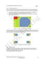
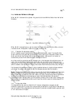
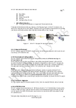
When HF-A11 modules boot up phase, the general user board MCU software flow chart will as
following:
Figure 12. User MCU Software Flow Chart
When HF-A11 modules boot up, user can select one work mode base on the setting, and user
can switch to the configuration mode at any kinds of work mode.
1.4.1. Transparent
Transmission
Mode
HF-A11 modules support serial interface transparent transmission mode. The benefit of this
mode is achieves a plug and play serial data port, and reduces user complexity furthest. In this
mode, user should only configure the necessary parameters. After power on, module can
automatically connect to the default wireless network and server.
As in this mode, the module's serial port always work in the transparent transmission mode, so
users only need to think of it as a virtual serial cable, and send and receive data as using a
simple serial. In other words, the serial cable of users’ original serial devices is directly replaced
with the module; user devices can be easy for wireless data transmission without any changes.
The transparent transmission mode can fully compatible with user’s original software platform
and reduce the software development effort for integrate wireless data transmission.
Notes
: Transparent transmission mode as a low level phy layer data transmitting can't keep zero
error rates by itself. User can enable UART port’s hardware flow control CTS/RTS function or
though higher layer protocol such as TCP to lower error rate and mange the data completeness.
High-Flying recommend when doing large amounts of data transmitting in transparent
transmission mode, hardware flow control should be enabled, so as to fully ensure reliable data
transmission. In the applications which doesn’t need flow control, users can simply leave RTS /
CTS pin vacant.
1.4.2. Configuration
Mode
In configuration mode, user can finish HF-A11 module configuration management and
parameters setting work. In work mode (Transparent Transmission or Agreement Transmission),
user can switch to the configuration mode through AT+instruction, detailed switch operation refer
to “AT+ instruction set” chapter.
High-Flying

