


32
FM 3180 Installation Guide
SFP LEDs
Each SFP port has one LED which indicates the following:
LED
Additional
Lit green
Indicates that the port is enabled and ready.
Flashing
Indicates that traffic is passing.
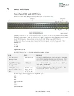
Management Panel
The following illustration identifies the management port (MGMT), serial console port (CONSOLE) and
USB port.
MGMT
: The MGMT port is an Ethernet port that is typically connected to the customer network and is
used for remote fabric module access for management. The MGMT port has two LEDs. Only the left
LED is used. The left LED lights when an active network is plugged in and flashes with network traffic.
CONSOLE
: The CONSOLE port can be used for serial access to the fabric module for management. The
CONSOLE port has no LED.
USB
: The USB port, located between the MGMT port and CONSOLE port, has no LED.
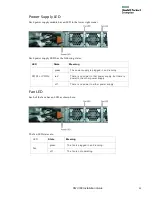
P-1
,
P-2
and
STAT
LEDs: The P-1, P-2 and STAT LEDs are described in the table below.
RST
: The I/O panel has a recessed RESET button for manual fabric module reset.
LED
State
State
P-1
Green
Power supply 1 (power supply labeled
PWR1) is plugged in and site power is on.
Off
Power supply PWR1 is not installed, the
power cord is not connected, or the site
power is off.
P-2
Green
Power supply 1 (power supply labeled
PWR1) is plugged in and site power is on.
Off
Power supply PWR1 is not installed, the
power cord is not connected, or the site
power is off.
STAT
Fast Flash
Started and is initializing.
Slow Flash
Initialized but has not yet connected to
HPE Control.
Solid Green
Connected to HPE Control and operating
properly.