


6.
Remove the air baffle (
7.
Remove the rear option blank (
Remove the rear drive cage blank).
Retain the rear option blank for future use.
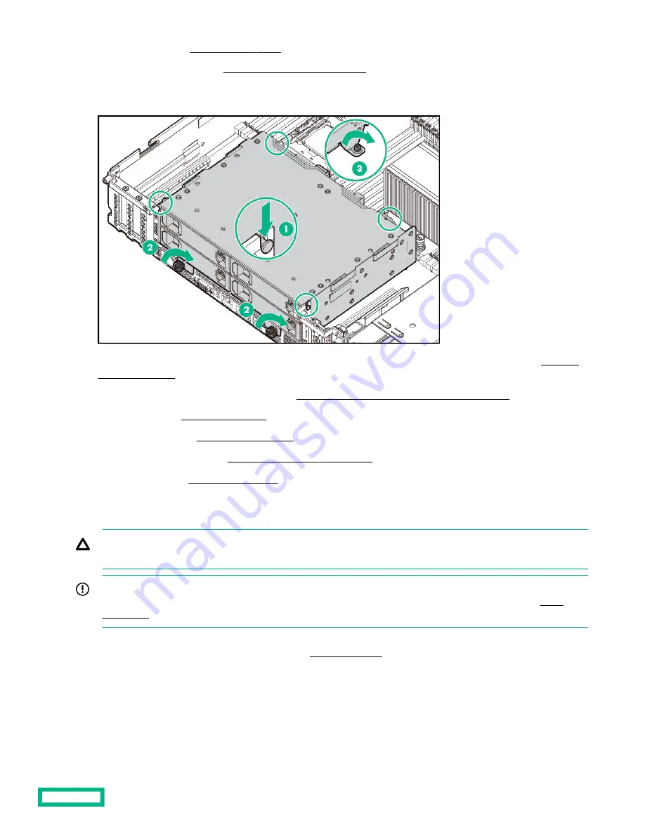
8.
Install the four-bay LFF hot-plug rear drive cage.
9.
10. Install the expansion board or type -p controller (Installing an expansion board or type -p controller).
11. Install the air baffle (Install the air baffle ).
12. Install the access panel (Install the access panel).
13. Install the system into the rack (Installing the system into the rack).
14. Power up the system (Power up the system).
Installing the two-bay SFF hot-plug rear drive cage and two-slot PCIe riser cage
CAUTION: For proper cooling do not operate the system without the access panel, baffles, expansion slot covers, or
blanks installed. If the system supports hot-plug components, minimize the amount of time the access panel is open.
IMPORTANT: Hewlett Packard Enterprise recommends installing at least one drive in the rear drive cage. Populate
drive bays based on the drive numbering sequence. Start from the drive bay with the lowest device number (
This drive cage option supports SFF SAS, SATA, and uFF drives. The SAS and SATA drives are assigned the drive numbers
49–50. The uFF drives are assigned 49-50 and 149-150 (
The PCIe riser cage option has two slots:
• PCIe3 x8 full-height, half-length slot
• PCIe3 x16 full-height, half-length slot
Hardware options installation
70


