background image

3. Installation 

instructions 

 
3.1. Connection information and start-up


The machine may only be connected by a qualified expert familiar with the machine 
to be operated (see section 4., “Maintenance”). 
 

The following also applies: 


Before starting any work on the switch cabinet or the receiver, switch off 


the power supply to the machine to be controlled. 


VDE regulations (German Association of Electrical Engineers), the 


regulations of local electricity supply companies, and German UVV 


(accident prevention) safety regulations must all be fulfilled. 


HETRONIC will not accept liability or provide a guarantee in the 


event of personal injury, damage to property and consequential 


damage resulting from improper or negligent handling of this  


product or from handling that does not comply with the  


regulations and standards on which these operating instructions 

  are 

based.


Take steps to ensure that the receiver is located in an easily accessible place and is 
not installed within the vehicle, the machine to be controlled, a switch cabinet or any 
other similar equipment. 
If installation in such a location is unavoidable, a projecting aerial must be mounted 
with it as well. Suitable projecting aerials can be obtained from your dealer. Please 
refer to section 3.3. of these operating instructions for installation information. 

 
Switch off the power supply to the machine before connecting the power 
supply unit of the receiver. 


Please refer to section 3.2. on the following page for the dimensions of 


the receiver and the drilling pattern. 


The radio remote control system may only be connected by a  


qualified expert familiar with the electrical circuitry of the machine 

  to 

be 

controlled. 


Summary of Contents for CS 434

Page 1: ...radio remote control systems of different transmitter versions from HETRONIC Please enter the system number here Please retain for reference Date of publication HETRONIC Adalbert Stifter Strasse 2 D 8...

Page 2: ...ogy All rights are reserved including those relating to photomechanical reproduction and to recording on electronic media The models illustrations and diagrams contained herein are the property of HET...

Page 3: ...ble batteries 2 1 2 Battery charger and charging the battery 2 1 3 Battery chargers 2 2 Control elements 2 3 Operation 2 3 1 Visual checks 2 3 2 Safety checks and starting the radio remote control sys...

Page 4: ...4 Maintenance 5 Disposal 6 Technical data 6 1 General 6 2 Rechargeable batteries and battery charger 6 3 Transmitter 6 4 Receiver 6 5 Standard options 7 Appendix A...

Page 5: ...ructed as required by regulations must strictly comply with the contents of these operating instructions 1 2 Safety information and tips The following symbols are used for warnings and advisory notes...

Page 6: ...r is responsible for ensuring that when the transmitter is put down it cannot be used by unauthorized persons This can be done either by pulling the key from the key switch by removing the rechargeabl...

Page 7: ...modified removed or bypassed under any circumstances or in any way whatsoever Additional protection devices depending on transmitter version Guard rim guard clip or recessed function buttons These saf...

Page 8: ...attery battery charger set 12 24 VDC or 115 230 VAC depending on the transmitter type and two HETRONIC interchangeable batteries or with a VersaPak rechargeable battery battery charger set 115 V AC or...

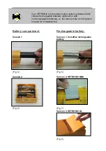
Page 9: ...three fully charged 1 5 V alkaline batteries in the battery compartment as depicted on the latter Insert the battery compartment in the battery receptacle of the transmitter with the contacts first a...

Page 10: ...NIC parts or parts approved by HETRONIC Not doing so introduces the risk of explosion Emitted chemicals and flying parts can cause injury Battery chargers from HETRONIC have a charge level recognition...

Page 11: ...VDC or 90 270 VAC After inserting the battery a yellow LED indicates the charging process When the battery is fully charged a green LED lights up When you switched to fast charge a red LED lights up...

Page 12: ...ies optional or with non rechargeable batteries i e the radio remote control system is ready for immediate use Battery compartment Rechargeable battery Version 1 Version 1 VersaPak rechargeable batter...

Page 13: ...ter version is included with these operating instructions The diagram forms part of the operating instructions The arrangement of the control elements and the transmitter labeling will vary subject to...

Page 14: ...nlock it see pictures 12 13 and 14 Now start the machine to be controlled If your transmitter has a green START button press it or start the transmitter by turning the key switch If your transmitter d...

Page 15: ...ger be possible to exercise control over any of the machine s functions Have you completed the checks and does the EMERGENCY STOP system function properly Now release the function button and unlock th...

Page 16: ...ce numbers correspond to the system address and therefore must be identical Operating time is too short Incorrect or run down rechargeable batteries non rechargeable batteries were inserted Check if t...

Page 17: ...0 1 0 434 2500 48 1 1 1 35 33 30 26 20 12 2 0 1 0 1 1 434 2750 49 0 1 1 0 0 434 3000 50 If FCS is selected 0 1 1 0 1 434 3250 51 the module will remember the last frequency that is set and then the 0...

Page 18: ...power is on 1 0 0 0 0 458 9000 16 If all channels are occupied the module will transmit at the least crowded 1 0 0 0 1 458 9250 17 channel 1 0 0 1 0 458 9500 18 1 0 0 1 1 458 9750 19 In AUTX mode the...

Page 19: ...or from handling that does not comply with the regulations and standards on which these operating instructions are based Take steps to ensure that the receiver is located in an easily accessible place...

Page 20: ...cluded with these operating instructions When mounting the receiver ensure that the aerial is positioned in such a way that it is minimally shielded by large metallic surfaces The receiver has an inte...

Page 21: ...11 poliger Sockel 11 pole socket 3 2 1 RX CP housing 11 pin socket View A A view...

Page 22: ...leranz DIN 7168 m Massstab 1 1 Werkstoff PA6 30 Glasfaser RAL1033 76 0 19 0 146 0 10 0 116 0 t 63 PG13 5 PG13 5 PG7 9 0 3 2 2 HS 1 housing Scale 1 1 Unit mm General tolerance DIN 7168 m Material PA6 3...

Page 23: ...0 231 0 7 8 115 8 22 1 PG21 t 89 0 Einheit mm Allgemeintoleranz DIN 7168 m Schutzart IP65 M 1 2 Werkstoff PA6 30 Glasfaser RAL1033 Scale 1 2 Unit mm General tolerance DIN 7168 m Material PA6 30 glass...

Page 24: ...3 2 4 Receiver housing 250 x 255 Scale 1 2 Unit mm General tolerance DIN 7168 m Attachment points 236 mm 200 5 mm 6 5 mm Scale 1 2 Unit mm General tolerance DIN 7168 m...

Page 25: ...3 2 5 Receiver housing 400 x 250 Scale 1 2 Unit mm General tolerance DIN 7168 m Attachment points 380x200 mm 6 5 mm...

Page 26: ...3 2 6 Receiver housing 400 x 400 o STEUERSYSTEME Ma e f r Befestigung 380x355 6 5 Einheit mm M 1 2 5 Atachment dimensions 380x355 6 5 M 1 2 5 Unit mm...

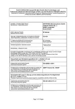
Page 27: ...ards guidelines and generally approved technical practice including DIN standards VDE standards and technical standards of other member states of the European Union or other states party to the conven...

Page 28: ...0 bps Main components Surface mounting modular construction Diagnosis Status displays for RF communication operating voltage displays for transmitter and receiver undervoltage display Certificates CE...

Page 29: ...t All relay outputs 275 VAC 8A Proportional resolution 8 bit 256 increments per function Built in ramp function selectable Proportional outputs PWM signal with selectable dither frequency and current...

Page 30: ......

Page 31: ......

Page 32: ...dinated with each other and tested and that all relevant safety provisions are maintained see section 2 Intended use Machine data Manufacturer Type description Serial number Year of manufacture Radio...

Reviews: