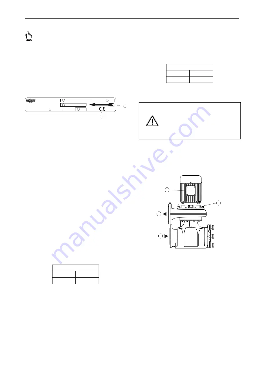
HERBORNER pumpentechnik UNIBAD-X Operating Manual Download Page 13

Safety

13

Figure 2  Name plate

Key to figure 2

1. Model designation
2. Year of manufacture/ month
3. Order No.
4. Nominal flow rate

[m

3

/h]

5. Nominal head

[m]

6. CE symbol
7. Observe the direction of rotation!

2.2 

Integrated safety systems (optional)

Check the integrated safety devices in regular inspection 

intervals 

j

 = annually.

The inspection methods applied here are:

S

 = Visual inspection, 

F

 = Functional check.

Winding protection

If the pump is also equipped with thermal winding protec-

tion with direct temperature monitoring, this switches off the 

pump's motor if it starts to get too hot.

Inspection

Interval

Method

j

S, F

 Important!

When making any inquiries and ordering spare parts 

please make sure you specify the pump type and the order 

number.
Also observe the name plate on the motor.

The name plate is attached to the fan hood or the motor 

housing (UNIBAD-XC).

ETS X4

An existing ETS X4 (electronic dry running protection system) 

that uses a vibrating fork sensor prevents the dry running 

of the slide ring seal. This protects the functionability of the 

pump.

Inspection

Interval

Method

j

S, F

Caution!
Incorrect warming will damage the 

three-phase motor.
Do not decommission safety equipment 

or change its mode of operation.

2.3 

Connections on the pump

Figure 3  Connections on the pump

The following connections are available on the pump:

1. Inlet connecting flange
2. Outlet connecting flange
3. Electric connection (terminal box)
4. Venting

1.

2.

3.

4.

Auftrag-Nr.

Q

Bj./ Mon.

m

m /h

3

1

3

4

5

2

6

UNIBAD

Pumpe

Herborner Pumpenfabrik

J.H. Hoffmann GmbH & Co. KG

Littau 3-5, DE-35745 Herborn

7

Summary of Contents for UNIBAD-X

Page 1: ...h water circulating pump Operating manual Model X XC X PM J H Hoffmann GmbH Co KG Littau 3 5 DE 35745 Herborn 49 0 27 72 933 0 49 0 27 72 933 100 info herborner pumpen de www herborner pumpen de Origi...

Page 2: ...l result in compensation for damages All rights reserved Translation Deliveries to countries of the EEA require the operating manual to be translated in accordance with the language spoken in the resp...

Page 3: ...Weygand Littau 3 5 35745 Herborn Germany We hereby declare that the Bath water circulating pump UNIBAD XC PM complies with all pertinent provisions of the EC Machinery Directive 2006 42 EC The machine...

Page 4: ......

Page 5: ...rotation check 26 5 6 1 Change of direction of rotation 27 5 7 Motor connection diagrams 27 5 7 1 PTC thermistor connection 28 5 8 Frequency converter operation 28 5 9 ETS X4 28 5 10 Laying the pipes...

Page 6: ...n indoor outdoor and adventure swimming baths water parks and ice sports recreation and hotel facilities for water slides attractions water treatment systems fountains heat recovery systems and indust...

Page 7: ...M Figure 1a Exploded view X X PM model Model XC Figure 1b Exploded view XC model 1 Only exists in case of design with screw propeller 2 Only exists in case of design with closed multi vane impeller in...

Page 8: ...ameter of pressure flange DN mm Design dimensions Hydraulic version Motor rating kW E g 030 3 0 kW Speed 4 1500 60 Hz 1800 min 1 Impeller version Model X standard XC Cooling jacket version Motor model...

Page 9: ...ces An existing ETS X4 permits monitoring of the mechanical seal to protect it from dry running 1 4 5 Drive Athree phase motor with squirrel cage drives the pump The motor is cooled by the dissipation...

Page 10: ...59 63 3 0 3 6 59 63 4 0 4 8 59 63 5 5 6 6 63 67 7 5 9 0 63 67 11 0 13 2 65 69 15 0 18 0 65 69 18 5 22 2 65 69 22 0 26 4 67 71 30 0 36 0 68 72 37 0 44 4 70 74 45 0 54 0 70 74 55 0 66 0 71 75 Motor data...

Page 11: ...49 53 3 0 3 6 49 53 4 0 4 8 49 53 5 5 6 6 49 53 7 5 9 0 49 53 11 0 13 2 50 54 15 0 18 0 50 54 18 5 22 2 52 56 22 0 26 4 52 56 30 0 36 0 52 56 Model X PM P2 kW 1500 min 1 1 1 52 1 5 55 2 2 55 3 0 55 4...

Page 12: ...pplication tips and other particularly useful information It is not a signal word for a dangerous or hazardous situation 2 1 1 Machine identification The information contained in this operating manual...

Page 13: ...e sure you specify the pump type and the order number Also observe the name plate on the motor The name plate is attached to the fan hood or the motor housing UNIBAD XC ETS X4 An existing ETS X4 elect...

Page 14: ...t standards to assess the work they have been assigned and are also able to identify any potential dangers 2 5 Obligations of the operator The operator is obligated to instruct his her operating and m...

Page 15: ...g and reparation of the pump 1 Only trained and authorised persons may install and operate the pump 2 Clearly define and observe the respon sibilities for operating the pump 3 Observe the shut off pro...

Page 16: ...ecialists Warning Electric current can result in death Disconnect the block motor 802 ac cording to the 5 safety rules When cleaning close any electrical cabinets that are open to prevent dust or wate...

Page 17: ...ust be designed to support the weight of the pump The driver must be authorised to operate the forklift truck 4 Transport 4 1 Scope of delivery The detailed scope of delivery can be viewed in the orde...

Page 18: ...section 5 2 Dimensions 4 3 2 Transport with a crane The crane must be able to support the full weight of the pump The operator must be authorised to oper ate the crane Attach the pump to the crane usi...

Page 19: ...s and be dimensioned in such a way that the star handles 004 on the filter cover 003 can be turned by hand Only then should the pump be installed The connection flanges must be perfectly aligned and s...

Page 20: ...evice 2 Main controlling dimensions of filter strainer Figure 5a Dimensions X X PM model Figure V Figure L Figure VR Figure VL Figure HL Figure H Figure HR Figure R 3 The terminal box alignment may va...

Page 21: ...300 380 260 290 27 340 18 543 300 213 100 271 0554X 100 150 950 275 260 270 800 425 291 260 150 300 380 260 290 27 340 18 519 300 188 100 271 0754X 100 150 965 275 260 270 800 425 291 260 150 300 380...

Page 22: ...80 260 290 27 340 18 543 300 198 100 271 0554X PM 100 150 925 275 260 270 800 425 291 220 150 300 380 260 290 27 340 18 519 300 174 100 271 0754X PM 100 150 950 275 260 270 800 425 291 258 150 300 380...

Page 23: ...e is sufficient room for the lifting device 2 Main controlling dimensions of filter strainer Figure 5b Dimensions XC model Figure V Figure L Figure VR Figure VL Figure HL Figure H Figure HR Figure R 3...

Page 24: ...00 150 920 275 260 270 800 425 291 218 150 300 380 260 290 27 340 18 519 300 163 100 331 1104XC 100 150 1015 290 260 270 800 440 291 258 150 300 380 260 290 27 340 18 550 1 227 100 333 1104XC 100 150...

Page 25: ...0 6 5 5 52 22 0 42 8 6 5 5 52 30 0 57 5 6 0 5 52 60 Hz 1800 min 1 460 V P2 kW I A IA IN 3 5 dB A 1 8 3 5 8 2 3 53 2 6 5 0 7 1 3 53 3 6 7 2 4 4 5 53 4 8 9 6 5 1 5 53 6 6 13 0 5 2 5 53 9 0 18 2 5 1 5 53...

Page 26: ...can result in death Provide equipotential bonding between the filter casing and building earth 5 5 Motor protection Use a motor circuit breaker or adequate motor protection with a tripping characteri...

Page 27: ...IBAD XC series the motor shaft has to rotate clockwise from the direction of the motor cover Openings in the intermediate casing allow a glimpse of the motor shaft W2 U2 V2 L1 L2 L3 U1 V1 W1 W2 U2 V2...

Page 28: ...5 9 ETS X4 For the mounting and electrical connection of the ETS X4 see the included operating instructions 5 10 Laying the pipes Lay the pressure pipes in accordance with the applicable regulations...

Page 29: ...ging 5 11 Soiling monitor of the filter strainer The degree of soiling of the filter strainer 002 can be checked via a digital pressure sensor or a pressure and vacuum gauge with shut off valve Attach...

Page 30: ...fill the pump and supply pipe with the pumped medium Then de aerate The ball valve 006 in the intermediate casing 113 is used for venting the pump For pumps of the type UNIBAD XC the ball valve 006 is...

Page 31: ...indicator to the displayed value 6 3 Operating modes and connecting frequency All models are designed for operating mode S1 continuous operation with a filled pump Figure 7 Screw connection label The...

Page 32: ...n temperature in the motor and an excessive load on the pump motor seals and bearing Contact the respective manufacturer with regard to the per missible switching frequency for any starter device 6 4...

Page 33: ...ing and top pling over Notice Pumped media can be hazardous to health Always wear personal protective equipment such as protec tive gloves and glasses The pump is subjected to vibrations during operat...

Page 34: ...g lubrication Anti friction bearings are provided pre lubricated Danger High magnetic forces during the disas sembly and assembly of PM motors can lead to severe personal injury and property damage Be...

Page 35: ...ion bearing drive side Anti friction bearing non drive side Greasing interval h Grease quantity g Greasing interval h Grease quantity g 1 1 1 3 5000 7 10000 3 1 5 1 8 5000 7 10000 3 2 2 2 6 5000 10 10...

Page 36: ...r than the starting value in case of a digital pressure sensor no longer corresponds with the locking indicator in the case of the pressure and vacuum gauge Important Before removing the filter strain...

Page 37: ...sembly as prescribed 7 8 Disposal The pump and individual components of the pump are to be disposed of in an environmentally friendly manner Contact your public or private disposal companies for furth...

Page 38: ...e Motor doesn t run Check the electri cal installation Gate valves closed Open gate valves Head too high Check the plant for any impurities and or the layout of the pump Disturbance Cause Trouble shoo...

Page 39: ...vement of the pump Pump switches too often Observe operat ing mode Motor connected incorrectly Connect motor to correct operating voltage Disturbance Cause Trouble shooting Bearing becomes hot Bearing...

Page 40: ...pecially for this purpose Observe the operating instructions included in delivery Important Tighten all nuts and bolts clockwise during assembly as prescribed see section 7 7 Tightening torques for nu...

Page 41: ...loosen the cooling water pipe 704 on the intermediate casing 113 1 Loosen the connecting bolts from the pump casing 101 and intermediate casing 113 2 Prise the complete inter changeable module on the...

Page 42: ...of the dismantled parts are to be checked for signs of damage and wear cleaned and replaced with original spare parts if necessary Important Nuts 920 with a self locking plastic ring are to be replac...

Page 43: ...egrease the shaft surface The pretension of the spring is obtained through the instal lation of the impeller 5 Carefully slide the rotating sliding ring with bellows and spring over the motor shaft sh...

Page 44: ...irection on the pump casing 101 2 Impeller gap too wide Place a shim behind the impeller 230 to compensate the air gap 13 Screw the pump casing 101 to the intermediate casing 113 Cooling hose mounting...

Reviews: