8
2
2..7
7 G
Ga
ass L
Le
ea
akk T
Te
esstt
T
To
o a
avvo
oiid
d ffiirre
e a
an
nd
d//o
orr e
exxp
pllo
ossiio
on
n,, n
ne
evve
err u
usse
e a
a lliig
gh
htte
ed
d m
ma
attcch
h o
orr o
op
pe
en
n fflla
am
me
e
tto
o tte
esstt ffo
orr g
ga
ass lle
ea
akkss.. IIg
gn
niitte
ed
d g
ga
ass cco
ou
ulld
d rre
essu
ulltt iin
n sse
evve
erre
e p
pe
errsso
on
na
all iin
njju
urryy
a
an
nd
d//o
orr p
prro
op
pe
errttyy d
da
am
ma
ag
ge
e..
NOTICE
:
Prior to turning the gas supply on, be sure the gas valve knob on the gas con-
trol valve is in the off position.
Upon initial installation, and after moving the unit, the piping and fittings should be
checked for gas leaks. A simple checking method is to turn on the gas and brush all
connections with a soap solution. If bubbles occur, it indicates escaping gas. In this
event, the piping connections must be redone.
2
2..8
8 G
Ga
ass P
Prre
essssu
urre
e R
Re
eg
gu
ulla
atto
orr S
Se
ettttiin
ng
g
The gas pressure regulator on the gas control valve is factory set as follows:
• Natural: 3.5 inch water column (0.87 kPa) (8.27 mbar).
• Propane: 10 inch water column (2.49 kPa) (24.9 mbar).
NOTE: The gas pressure regulator has been set by Henny Penny and is not to be
adjusted by the user.
2
2..9
9 E
Elle
eccttrriicca
all R
Re
eq
qu
uiirre
em
me
en
nttss
•
T
To
o a
avvo
oiid
d e
elle
eccttrriicca
all ssh
ho
occkk,, tth
hiiss a
ap
pp
plliia
an
ncce
e m
mu
usstt b
be
e e
eq
qu
uiip
pp
pe
ed
d w
wiitth
h a
an
n
e
exxtte
errn
na
all cciirrccu
uiitt b
brre
ea
akke
err w
wh
hiicch
h iin
ncco
orrp
po
orra
atte
ess a
a 3
3 m
mm
m d
diisscco
on
nn
ne
eccttiio
on
n iin
n
a
allll u
un
ng
grro
ou
un
nd
de
ed
d ((u
un
ne
ea
arrtth
he
ed
d)) cco
on
nd
du
ucctto
orrss.. T
Th
he
e m
ma
aiin
n p
po
ow
we
err ssw
wiittcch
h iin
n
tth
hiiss a
ap
pp
plliia
an
ncce
e d
do
oe
ess n
no
ott d
diisscco
on
nn
ne
ecctt a
allll lliin
ne
e cco
on
nd
du
ucctto
orrss..
•
T
To
o a
avvo
oiid
d e
elle
eccttrriicca
all ssh
ho
occkk,, d
do
o n
no
ott d
diisscco
on
nn
ne
ecctt tth
he
e g
grro
ou
un
nd
d ((e
ea
arrtth
h)) p
pllu
ug
g..
T
Th
hiiss ffrryye
err m
mu
usstt b
be
e a
ad
de
eq
qu
ua
atte
ellyy a
an
nd
d ssa
affe
ellyy g
grro
ou
un
nd
de
ed
d ((e
ea
arrtth
he
ed
d)).. R
Re
effe
err
tto
o llo
occa
all e
elle
eccttrriicca
all cco
od
de
ess ffo
orr cco
orrrre
ecctt g
grro
ou
un
nd
diin
ng
g ((e
ea
arrtth
hiin
ng
g)) p
prro
occe
ed
du
urre
ess
o
orr iin
n a
ab
bsse
en
ncce
e o
off llo
occa
all cco
od
de
ess,, w
wiitth
h T
Th
he
e N
Na
attiio
on
na
all E
Elle
eccttrriicca
all C
Co
od
de
e,,
A
AN
NS
SO
O//N
NF
FP
PA
A N
No
o.. 7
70
0--((tth
he
e ccu
urrrre
en
ntt e
ed
diittiio
on
n)).. IIn
n C
Ca
an
na
ad
da
a,, a
allll e
elle
eccttrriicca
all
cco
on
nn
ne
eccttiio
on
nss a
arre
e tto
o b
be
e m
ma
ad
de
e iin
n a
acccco
orrd
da
an
ncce
e w
wiitth
h C
CS
SA
A C
C2
22
2..2
2,,
C
Ca
an
na
ad
diia
an
n E
Elle
eccttrriicca
all C
Co
od
de
e P
Pa
arrtt 1
1,, a
an
nd
d//o
orr llo
occa
all cco
od
de
ess..
NOTICE
:
Disconnect power supply before a thorough cleaning or servicing the fryer.
•
120 V; 50/60 Hz; 1 PH; 12 A
•
230 V; 50 Hz; 1 PH; 7 A
The 120 volt gas fryer is factory equipped with a grounded (earthed) cord and plug for
your protection against shock, and should be plugged into a three-prong grounded
(earthed) receptacle. Do not cut or remove grounding (earthing) prong. Any 230 volt
unit must conform to all local, state, and national codes.
Summary of Contents for Wendy's Evolution Elite EEG-251
Page 2: ......
Page 5: ...Contents iii...
Page 14: ...Introduction 2...
Page 19: ...Installation 7 Figure 2 1 Flexible Gas Line Cable Restraint Installation...
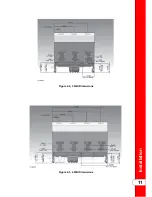
Page 22: ...Figure 2 2 1 Well Dimensions Figure 2 3 2 Well Dimensions Installation 10...
Page 23: ...Figure 2 4 3 Well Dimensions Figure 2 5 4 Well Dimensions Installation 11...
Page 24: ...Installation 12...
Page 51: ...Operation 37...
Page 62: ...Operation 48...
Page 68: ...Information Mode 54...
Page 72: ...Product Program Mode 58...
Page 87: ...Troubleshooting 73...
Page 88: ...Troubleshooting 74...
Page 89: ...blank page...


