


7. Compensation Procedures
7.1
Series Resistance Compensation
In whole cell voltage clamp recording, the membrane potential of the cell is controlled by the potential applied to
the pipette electrode. This control of potential is not complete, but depends on the size of the access resistance
between the pipette and the cell interior, and on the size of the currents that must flow through this resistance.
This access resistance is called the series resistance (Rs) because it constitutes a resistance in series with the pipette
electrode. Part of the series resistance arises from the pipette itself, but normally the major part arises from the
residual resistance of the broken patch membrane, which provides the electrical access to the cell interior. In
practice, we find that the series resistance usually cannot be reduced below a value about two times the resistance
of the pipette alone.
Series resistance has two detrimental effects in practical recording situations. First, it slows the charging of the
cell membrane capacitance because it impedes the flow of the capacitive charging currents when a voltage step
is applied to the pipette electrode. The time constant of charging is given by
τ
u
=
R
s
∗
C
m
, where
C
m
is the
membrane capacitance. For typical values of
R
s
= 5
M
Ω and
C
m
= 20
pF
, the time constant is 100
µs
. This
time constant is excessively long for studying rapid, voltage-activated currents such as
N a
+
currents in neurons,
especially since several time constants are required for the membrane potential to settle at its new value after a
step change. The second detrimental effect of series resistance is that it yields errors in membrane potential when
large membrane currents flow. In the case of
R
s
= 5
M
Ω, a current of 2 nA will give rise to a voltage error of
10 mV, which is a fairly large error; for studying voltage-activated currents, errors need to be kept to
∼
2 mV at
most.
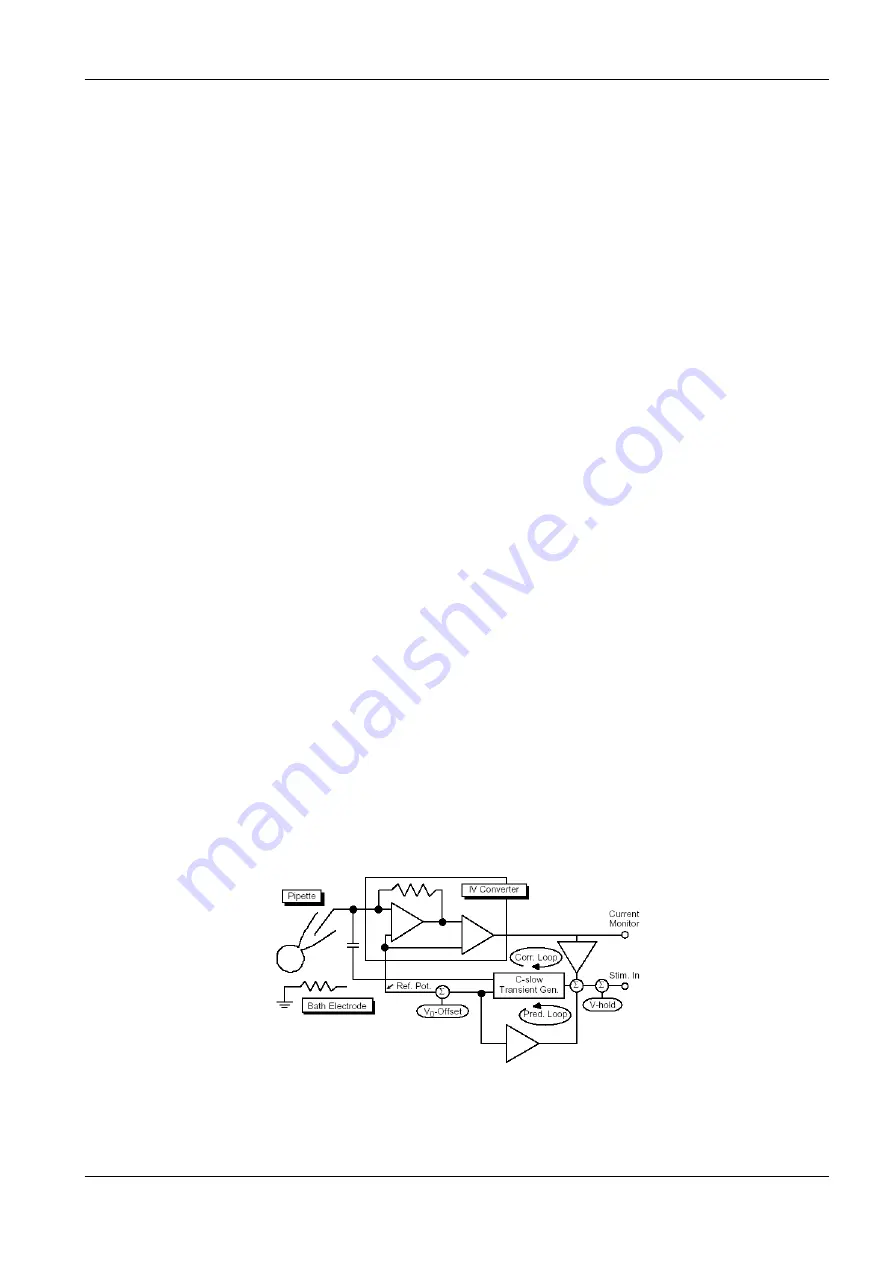
Electronic compensation for series resistance in voltage clamp systems has been in common use since the days of
Hodgkin and Huxley. The principle of the compensation in the case of a patch clamp is that a fraction of the
current monitor signal is scaled and added to the command potential (correction pathway, see figure below). When
a large current flows in the pipette, the pipette potential is altered in a way that compensates for the potential
drop in the series resistance. This arrangement constitutes positive feedback, and can become unstable when
overcompensation occurs.
The
EPC 10 USB
incorporates additional circuitry to allow capacitance transient cancellation to occur while
Rs-compensation is in use (see Sigworth, Chapter 4 in Single-Channel Recording). This is shown as the prediction
pathway in the figure below, and it accelerates the charging of the membrane capacitance by imposing large,
transient voltages on the pipette when step changes are commanded (this is sometimes called ”supercharging”).
These voltages would occur due to the action of the correction pathway alone as the large capacitive charging
currents elicit pipette voltage changes; however, when these currents are canceled by the transient cancellation,
their effect must be predicted by the cancellation circuitry: hence the prediction pathway.
Figure 7.1: Series Resistance compensation circuit
Summary of Contents for EPC 10 USB
Page 1: ...Hardware Manual Version 2 8 EPC 10 USB Computer controlled Patch Clamp Amplifier...
Page 6: ......
Page 10: ...4 Introduction http www heka com...
Page 16: ...10 Description of the Hardware http www heka com...
Page 22: ...16 Installation http www heka com...
Page 32: ...26 Verifying and Testing the EPC 10 USB http www heka com...
Page 44: ...38 The control software http www heka com...
Page 48: ...42 Operating Modes http www heka com...
Page 54: ...48 Compensation Procedures http www heka com...
Page 58: ...52 Patch Clamp Setup http www heka com...
Page 64: ...58 Using the Patch Clamp http www heka com...
Page 74: ...68 Appendix II Probe Adapters http www heka com...
Page 76: ...70 Appendix III S Probe http www heka com...
Page 81: ......