Installation
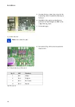
Fig. 69 PCB 00.785.1151
Note:
Use a dielectric pen!
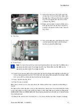
Fig. 70 Reset button S3 and DIP switch S2
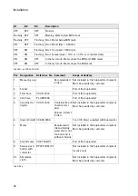
Tab. DIP switch S2
5.
Unscrew the two screws from above for the
bracket (Fig. 68/3) to which the filler hose is
fastened.
6. Plug X158 of the service pushbutton (see
position 9 in Table
/3) to X158 on the
chiller PCB (Fig. 69/1).
7.
Fit bracket again.
8. Set switch 3 (Fig. 70/3) of microswitch S2
down to OFF.
DIP
Function
1
S2-1
Chiller
2
S2-2
Program
3
S2-3
Test mode
4
S2-4
Buzzer
i
i
Summary of Contents for Suprasetter A52
Page 6: ......
Page 24: ...Safety 22 Fig 24 Filter replacement Fig 13 4 On the filter unit ...
Page 26: ...Safety 24 Fig 26 Warning sign copy template ...
Page 36: ...Installation Preparation 34 Pallet Installation Instructions ...
Page 82: ...Technical Data 80 Resolution 1000 pixels cm 2540 dpi Type Value Comment ...
Page 84: ......
Page 85: ......

