Installation
Suprasetter A52/A75 – Installation
Power Connection
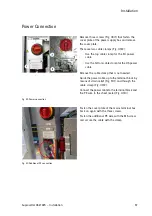
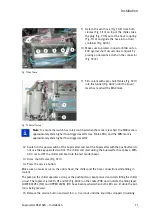
Fig. 49 Power connection
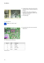
Fig. 50 Additional PE connection
Remove three screws (Fig. 49/1) that fasten the
cover plate of the power supply box and remove
the cover plate.
There are two cable clamps (Fig. 49/2).
• Use the top cable clamp for the EU power
cable.
• Use the bottom cable clamp for the US power
cable.
Remove the cable clamp that is not needed.
Guide the power cable up to the terminal block by
means of strain relief (Fig. 51/1) and through the
cable clamp (Fig. 49/2).
Connect the power cable to the terminal block and
the PE wire to the sheet metal (Fig. 49/3).
Fasten the cover plate of the mains terminal box
back on again with the three screws.
Fasten the additional PE wire with the M5 screw
and secure the cable with the clamp.
Summary of Contents for Suprasetter A52
Page 6: ......
Page 24: ...Safety 22 Fig 24 Filter replacement Fig 13 4 On the filter unit ...
Page 26: ...Safety 24 Fig 26 Warning sign copy template ...
Page 36: ...Installation Preparation 34 Pallet Installation Instructions ...
Page 82: ...Technical Data 80 Resolution 1000 pixels cm 2540 dpi Type Value Comment ...
Page 84: ......
Page 85: ......


