14
Setting Up the Fence
Boundary/Trigger Zone
3
Setting Up the Fence Boundary
Fen
ce B
ou
nd
ary
/Tr
ig
ge
r Z
o
n
e
Illustration D
Havahart
®
Radial-Shape Wireless Dog Fence
1-800-800-1819, Option 1
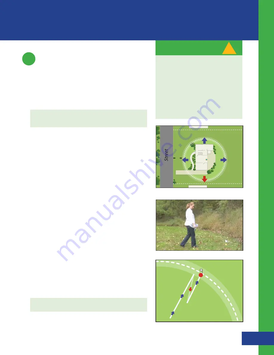
Establishing the Fence Boundary/Trigger Zone Distance:
1.
Estimate the distance between the Controller and the
desired boundary location. This distance will be the radius
of the Trigger Zone all the way around the Controller.
TIP :
Use the shortest distance to a physical boundary as a
starting point for the radius of the Trigger Zone (see Illustration C).
2.
Set the radius on the Controller
s
From the Set Up Menu, select Fence Setup (see Screen 1.7)
s
Use the up/down arrow to scroll to the desired radial
distance and press Enter. The minimum radius is 40 feet,
and the maximum radius is 400 feet from the Controller
in all directions (see screen 2.1).
s
Select OK to Save Your Settings
3.
Test the Trigger Zone
s
To confirm that the location of the actual boundary is
correct...
- Hold the Collar by the strap with your arm fully
extended down by your side (see Figure 1.6). Make
sure that your body does not get between the Collar
and the Controller as your body may affect the signal
and cause the boundary to shift inward (see Factors
Affecting Signal Strength on page 32).
- Walk toward the boundary while gently moving the
Collar until the Collar beeps and the Collar light flashes
red. To confirm that the distance is correct, step back 6
feet until the Collar stops beeping and then walk in the
same direction until the Collar beeps and the Collar light
flashes red again. Note how far from desired location
the actual setting is.
4.
Adjust the Fence Distance on the Controller accordingly
using the instructions in Step 2 until the desired boundary
location is established.
TIP :
Place a flag at the boundary location (see Illustration D).
Your Trigger Zone should be NO closer
than 6 feet to ANY ROAD, SIDEWALK
OR THOROUGHFARE FOR YOUR DOG’S
SAFETY.
The actual distance from the Trigger
Zone to the Controller may be less than
the set radius. This reduced boundary
may be the result of Factors Affecting
Signal Strength (page 32).
!
IMPORTANT MESSAGE
RO
AMING ARE
A
10 ’
Figure 1.6
Illustration C


