MODU-FIRE
®
Forced Draft Gas-Fired Boiler 2500-3000
10
3.3.3 Installation
Clearances
If the boiler is to be installed near combustible surfaces, six (6”) inches minimum clearance to the combustible
surface must be maintained.
Failure to provide for the service access clearances, even with non-combustible surfaces, may cause future
problems servicing the boiler.
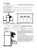
The boiler must be installed in a space large in comparison to the boiler as described in the National Fuel Gas
Code, NFPA 54/ANSI Z223.1, Latest Edition.
C
A
B
C
A
B
Clearances from Adjacent Walls, Ceiling,
and Obstructions Side Clearances for a Row of Boilers
† "C" dimension includes clearance to remove
the burner and installation of the air inlet duct.
Do not put pipes, other ducts, equipment, etc.
above the boiler.
* CSA minimum. Actual clearance depends upon
venting requirements.
** Service access need be only on one side of a
boiler or row of boilers. Boilers may be installed immediately
adjacent to each other. However, Harsco Industrial,
Patterson-Kelley recommends this clearance between
each
boiler
when there is insufficient access at the rear to allow
for service and adjustment.
3.4 E
LECTRICAL
C
ONNECTIONS
All field wiring connections for power and controls are in the
junction box on the back of the boiler. The boiler wiring label
is attached to the inside front door of the boiler. An external
electrical disconnect (not supplied with the boiler) with
adequate overload protection is required. The boiler must be
grounded in accordance with local codes or in the absence of
such requirements, in the U.S. with National Electrical
Codes, ANSI/NFPA No. 70 latest edition and in Canada, wire
according to the current Canadian Electrical Code.
Type of Surface
Dimensions (inches)
A B C† D
CSA Minimum Clearances to
Combustibles
24 24* 24 24
Recommended Service
Clearances
30 24* 24 24**
D
D
Electrical
Connections
Summary of Contents for 1004905923
Page 2: ...MODU FIRE Forced Draft Gas Fired Boiler 2500 3000 2 ...
Page 45: ...MODU FIRE Forced Draft Gas Fired Boiler 2500 3000 45 6 1 3 Wiring Schematic ...
Page 48: ...MODU FIRE Forced Draft Gas Fired Boiler 2500 3000 48 6 1 6 Rear Junction Box ...
Page 49: ...MODU FIRE Forced Draft Gas Fired Boiler 2500 3000 49 6 1 7 Customer Connections ...
Page 56: ...MODU FIRE Forced Draft Gas Fired Boiler 2500 3000 56 ...


