Section-5 Maintenance
October 28, 2013
5
‐
26
Copyright
©2013,
Harris
Broadcast
WARNING:
Disconnect
primary
power
prior
to
servicing.
888
‐
2720
‐
001
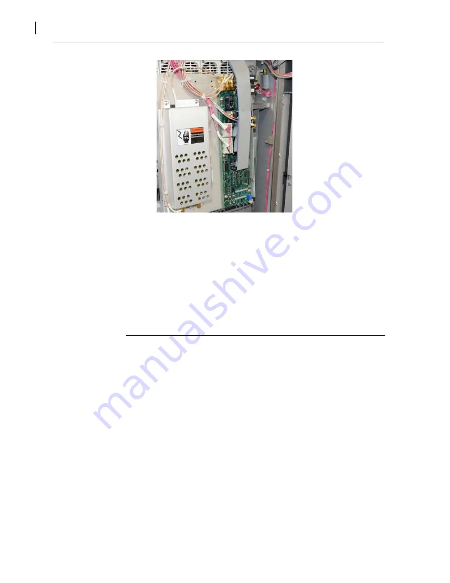
Figure 5-16 Remove Multi Unit System Interface Control Module Cables
After the Module is removed, use a Phillips screw driver to remove the PWA from the metal housing it attached to by
removing 6 Phillips screws. Attach the replacement PWA to the metal housing. Set the dipswitches to match the
removed boards on Rev E and higher PWA’s. If replacing a PWA Rev D or earlier refer to Section 5.4.4 for a
description of each switch. The board will come in the factory default positions.
Verify that the system power calibration is still correct.
5.8.4
Control and Display Board Replacement
The
following
steps
explain
how
to
change
the
Control
and
Display
Board.
The
transmitter
configuration
is
stored
on
this
board,
if
this
file
was
not
downloaded
from
the
transmitter
and
stored,
a
copy
can
be
obtained
from
Harris
Broadcast.
However,
this
file
will
not
have
nay
changes
that
have
been
made
since
it
left
the
Harris
Broadcast
factory.
If
Ethernet
connectivity
is
still
available,
got
to
5.5.1
in
this
section
of
the
manual
and
download
the
file
prior
to
removal
of
the
board.
STEP 1
Remove
all
AC
power
to
the
transmitter.
STEP 2
The
Ethernet
cable
catch
is
located
between
the
board
and
the
connector,
it
may
easiest
to
wait
until
the
board
is
removed
from
the
door
and
then
carefully
use
a
small
screw
driver
to
press
the
catch
and
remove
the
cable.
Remove
all
cables
from
the
board.
STEP 3
Remove
the
board
from
the
front
door.
Remove
the
Ethernet
cable
if
not
already
done.
STEP 4
If
the
replacement
board
does
not
have
a
Micro
Module
attached,
the
existing
one
can
be
reused.
STEP 5
If
required
install
existing
Micro
to
new
board
and
install
the
board
back
on
the
front
door.
STEP 6
Replace
all
cables
STEP 7
Turn
on
the
AC
power
and
connect
computer
to
one
of
the
Ethernet
ports.
STEP 8
Upload
a
configuration
file
to
the
transmitter.
See
Section
5.5.1
in
this
section
of
the
manual
for
procedure.
STEP 9
Turn
transmitter
on
and
verify
correct
operation.
Summary of Contents for Flexiva FAX 10KW
Page 2: ......
Page 8: ......
Page 10: ...WARNING Disconnect primary power prior to servicing ...
Page 167: ......


