Appendix A: Graceful Startup/Shutdown Procedure
77
Vision
2
Instruction Manual
Appendix A: Graceful Startup/Shutdown Procedure
Overview
In the event of a planned or unplanned network or electrical outage, the following steps should be taken to ensure a controlled
shutdown and restart of the IPTV system. The order of restart is critical to provide data to the control components as to last
operating configuration. If the system is brought back into service randomly or in improper order, it may perform with unexpected
behaviors.
Shutdown
The order of shutdown is not as critical as the restarting, but the recommended order and tasks are:
1.
Client
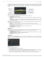
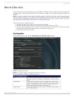
servers - gracefully shutdown using keyboard and mouse attached to server (FIG.
To login, enter the username Administrator, and the default password Vision2.
From the Windows desktop, navigate to Start and select Shut Down.
2.
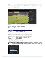
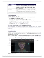
DTV-MA01 TDS Management Appliance- gracefully shutdown using keyboard and mouse attached to unit.
To login, enter the username amxdtv, and the password admin.
From Windows desktop, navigate to Start and select Shut Down.
As an alternative, press and hold the power button on the front face of the unit until activity and power indicator lights turn off
3.
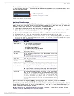
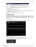
DTV-TX03 Transmitter - power off unit by disconnecting power cable from rear of unit (FIG. 111).
4.
STB-04 Vision
2
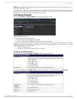
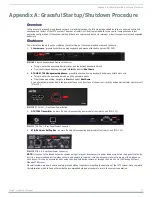
Set-Top Box - power off unit by disconnecting power cable from rear of unit (FIG. 112).
NOTE: In the event of a planned network or power outage it may not be necessary to power down every Amino throughout the facility,
but it is a recommended practice. When network and power are restored, it may be necessary to select a program to be played on
each Amino. This can be accomplished by using the hand-held Amino remote, or through the Vision2 UI in the Manage System >
Manage STB screens.
When all systems are down, you can safely proceed without negatively impacting the operation of the IPTV system. Once complete,
the information which follows will provide the recommended startup procedure to return the system to operation.
FIG. 109
Attach a Keyboard and Mouse to the Server
FIG. 110
DTV-MA01 - Front Panel Power Button
FIG. 111
TDS-TX03 - Rear Panel Power Connector
FIG. 112
STB-04 - Rear Panel Power Connector

