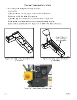
9. Remove the eight screws that secure the wireway to the machine.
10. Carefully lift the pendant and wireway.
11. Rotate the pendant to the operating position at the front of the machine. DO NOT set into
position at this time.
12. Connect cable 3009.
13. If the machine is equipped with the optional part present detector, connect cable 5739.
14. Feed any excess wires and cables into the machine wire duct.
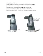
15. Apply a bead of silicone sealant around the lower front attachment points, shown in Figure 1.26.
16. Guiding the threaded stuns on the pendant into the upper and lower front attachment points,
Figures 1.26 and 1.27, set the pendant into position.
17. Inside the machine, install two flange nuts at the upper front attachment points.
18. Inside the machine, install four flange nuts at
the lower front attachment points.
19. Install access cover "M", Figure 1.22.
20. At the top of the machine, install the eight
screws to secure the wireway to the machine.
21. Install the wireway top cover.
22. Remove lifting bracket “N”, Figure 1.23, from
the back of the pendant.
23. Remove lower shipping bracket “O”, Figure
1.24, from the right end of the machine.
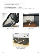
24. Install right end access cover "Q", Figure 1.28,
on the machine.
M-507C
1-17
Figure 1.26 - Lower Front Attachment Point
TP8353
Lower Front
Attachment Points
Figure 1.27 - Upper Front Attachment Point
TP8349
Upper Front
Attachment Points
Figure 1.28 - Right End Access Cover
TP7961
Q
Summary of Contents for T-42
Page 8: ... NOTES vi M 507C ...
Page 50: ... NOTES 1 42 M 507C ...
Page 84: ... NOTES 2 34 M 507C ...


