


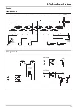


8 - Technical specifications
93
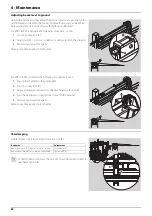
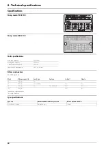
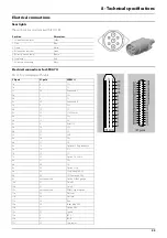
Electrical connections
Rear lights
The wiring is in accordance with ISO 1724.
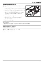
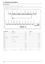
Electrical connections for SPRAY II
39- or 37-poled plug with cable.
Position
Wire colour
1. LH direction indicator
Yellow
2. Free
Blue
3. Frame
White
4. RH direction indicator
Green
5. RH rear position lamp
Brown
6. Stop lamps
Red
7. LH rear position lamp
Black
39-pole
37-pole
SPRAY II
1a
5
S1+
1b
6
S1-
1c
26
End nozzle L
2a
7
S2+
2b
8
S2-
2c
25
End nozzle R
3a
9
S3+
3b
10
S3-
3c
29
+12V sensor
4a
11
S4+
4b
12
34-
4c
4
PWM 1TX
5a
14
S5+
5b
15
S5-
5c
27
GND
6a
16
S6+
6b
17
S6-
6c
13
Optional 5 Reg. feedback
7a
18
S7+
7b
19
S7-
7c
33
Option 1 4-20mA
8a
37
S8+
8b
36
S8-
8c
32
Option 2 Frq
9a
35
S9+/Air angle 0-5V
9b
34
S9-/Fan speed 0-5V
9c
not connected
Option 3/Tank gauge
10a
21
On/off+
10b
22
On/off-
10c
not connected
PWM Output option
11a
23
P
11b
24
Pressure-
11c
28
Flow
12a
20
Foam blop 0-5V
12b
1
Option 4 Rx
12c
31
Speed
13a
3
FM L
13b
2
FM R
13c
30
Gnd sensor
Summary of Contents for RANGER EAGLE
Page 8: ...1 EC Declaration 8 ...
Page 12: ...2 Safety notes 12 ...
Page 26: ...3 Description 26 ...
Page 40: ...4 Sprayer setup 40 ...
Page 60: ...5 Operation 60 ...
Page 84: ...6 Maintenance 84 ...
Page 95: ...8 Technical specifications 95 Charts Boom hydraulic Z Boom hydraulic Y ...
Page 96: ...8 Technical specifications 96 ...
Page 100: ...HARDI INTERNATIONAL A S Helgeshøj Allé 38 DK 2630 Taastrup DENMARK ...


