


3 - Description
17
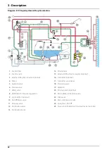
Liquid system
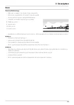
Pump
Diaphragm pump with 3 diaphragms, model 1303 or diaphragm pump with 6 diaphragms, model 363. Standard = 540 r.p.m.
(6 splines shaft). The design of the diaphragm pump is simple, with easily accessible diaphragms and valves which ensures
liquid does not contact the vital parts of the pump.
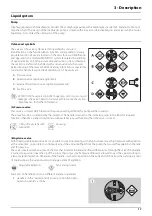
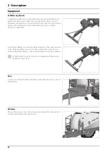
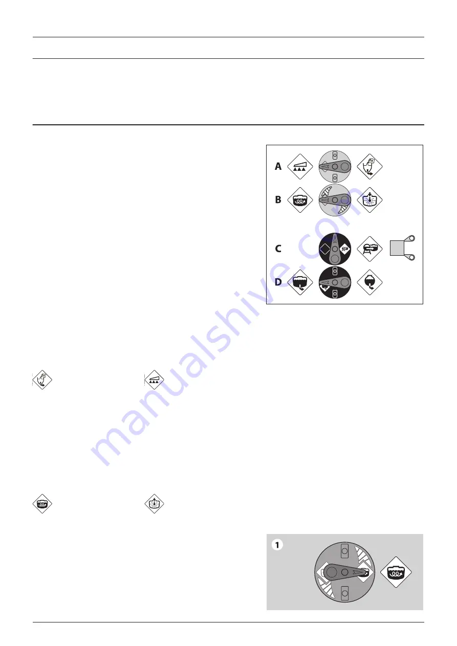
Valves and symbols
The valves at the valve system are distinguished by coloured
identification on the function labels. Symbols corresponding to every
possible function of use are located on the discs for easy identification
and operation. The modular MANIFOLD system facilitates the addition
of optional extras on both pressure side and suction side. Furthermore
the suction manifold can be fitted with a return valve which ensures
better draining of the sprayer before cleaning. A function is activated by
turning the handle towards the desired function. The valves are:
A.
Pressure valve
B.
Agitation valve (optional equipment)
C.
External filling device valve (optional equipment)
D.
Suction valve
μ
ATTENTION! If a valve is too tight to operate - or to loose (= liquid
leakage) - the valve needs to be serviced. Please see the section
‘Maintenance’ for further information.
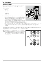
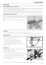
(A) Pressure valve
This valve is to select which function the pressurized liquid from the pump will be routed to.
The active function is indicated by the indicator. The handle is turned so the indicator points to the label for required
function. If handle is turned to a position without label (unused function) then the valve is closed.
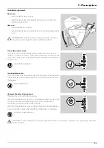
(B) Agitation valve
With the adjustable Agitation valve it is possible to combine spraying with a high volume rate at high pressure with agitation
at the same time, i.e. possible to continously adjust the amount of fluid from the pump that is used for agitation in the tank
and for spraying.
The valve is marked with an arrow on the disc that indicates the amount of liquid that passes through the valve. If the handle
is turned to a position near the tip of the arrow, then only a small amount of liquid is allowed to pass the valve resulting to
a lesser extent of agitation. Otherwise if the handle is turned to a position in the wide end of the arrow then a large amount
of liquid will pass the valve resulting to a large extent of agitation.
Examples on handle positions at different agitation quantities:
1.
Handle is in the “widest end of arrow” position (full open).
Agitation quantity is 100%.
Filling of main tank with
TurboFiller
Spraying
Adjustable Agitation
Tank rinsing nozzle
Summary of Contents for RANGER EAGLE
Page 8: ...1 EC Declaration 8 ...
Page 12: ...2 Safety notes 12 ...
Page 26: ...3 Description 26 ...
Page 40: ...4 Sprayer setup 40 ...
Page 60: ...5 Operation 60 ...
Page 84: ...6 Maintenance 84 ...
Page 95: ...8 Technical specifications 95 Charts Boom hydraulic Z Boom hydraulic Y ...
Page 96: ...8 Technical specifications 96 ...
Page 100: ...HARDI INTERNATIONAL A S Helgeshøj Allé 38 DK 2630 Taastrup DENMARK ...


