background image

45

GB 14 07 04

Approx. oil quantity:  1.0 l (35.2 fl.oz.)

Regarding oil quality, see section on “Lubricants”

6.  Refit the dip stick and filling plug - retighten.

Disposal of waste oil must only be carried out in accord-
ance with local legislation.

5. Hy

5. Hy

5. Hy

5. Hy

5. Hydr

dr

dr

dr

draulic tank air f

aulic tank air f

aulic tank air f

aulic tank air f

aulic tank air filter

ilter

ilter

ilter

ilter

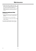
Change the hydraulic tank breathing filter.

1.  Clean the area

around the air filter
thoroughly.

2.  Remove screw 

A

,

washer 

B

 and cap 

C

.

3.  Renew the filter

cartridge D.

4. Reassemble in

reverse order.

T191-0011

Summary of Contents for MARRO TWIN FORCE 1000

Page 1: ...le omissions or inaccuracies in this publication although everything possible has been done to make it complete and correct As this instruction book covers more models and features or equipment which are available in certain countries only please pay attention to paragraphs dealing with precisely your model MARRO TWIN FORCE Instruction book 674156 GB 2001 04 We congratulate you for choosing a HARD...

Page 2: ...2 ...

Page 3: ...tments of EC operating unit 21 By pass valve 21 Remote pressure gauge 21 Filters 22 Filling of chemicals 22 Filling through tank lid 22 Filling by HARDI FILLER chemical inductor 23 Filling by HARDI FILLER chemical inductor 24 Use of rinsing tank and rinsing nozzles if fitted 25 Technical Residue 25 Operation of the tank drain valve 26 Rinsing tank drain valve 26 Safety precautions 26 Personal prot...

Page 4: ...ions in the COUNCIL DIRECTIVE of 14 June 1989 on mutual approximation of the laws of the Member States on the safety of machines 89 392 EEC as amended by directives 91 368 EEC and 93 368 EEC with special reference to Annex 1 of the Directive on essential safety and health requirements in relation to the construction and manufacture of machines B was manufactured in conformity with the current stan...

Page 5: ...d before servicing Never service or repair the equipment while it is operating Disconnect electrical power before servicing Always replace all safety devices or shields immediately after servicing If an arc welder is used on the equipment or anything connected to the equipment dis connect power leads before welding Re move all inflammable or explosive material from the area Do not eat drink or smo...

Page 6: ...T O revolutions are between 300 600 r min for pump 540 r p m or 650 1100 r min for pump 1000 r p m The operating unit is fully electrically controlled EC via remote control box Filters With the self cleaning filter the impurities that exist in the spray liquid will by pass the filter and be recirculated back to the tank via the return flow Also suction filter and nozzle filters are standard In lin...

Page 7: ...and for parking the front tank when not used is available ref no 833269 Bef Bef Bef Bef Befor or or or ore putting the spr e putting the spr e putting the spr e putting the spr e putting the spra a a a ay y y y yer into er into er into er into er into oper oper oper oper opera a a a ation tion tion tion tion Although the sprayer has been applied with a strong and protective surface treatment on st...

Page 8: ...part Connecting the MARRO lift for further information Fit the two reinforcement mountings on the linkage frame as shown on the drawing Fasten each with two bolts M16 x 50 Tractor without front lift A base plate for hook on attachment ref no 161594 must be used as interface between tractor and front tank This plate needs to be welded to two longitudinal bear ers which subsequently can be bolted to...

Page 9: ...t the top bar secure with pins 6 Lift the sprayer 7 Retract each of the four support legs Retraction of support legs 1 Remove the lock pin 2 Push up the support leg till the lower hole B in the inner profile matches the hole C in the outer profile 3 Fasten this position by the pin A 4 Position the tractor lift so the boom can be lowered to 45 50 cm in lowest position and adjust top bar until the g...

Page 10: ...t tank Distance 20 cm Attach the hoses with fittings to the fronttank 1 Self Cleaning Filter 2 Suction 3 HARDI Filler 4 Agitation Pull out the step at front to get acces to the top of the tank The hoses are led from the MANI FOLD valves along the side of the tractor to the front tank as shown on the drawing Routing of hoses will vary depending on tractor model 1 2 3 4 ...

Page 11: ...rans mission shaft or implement T T T T Tr r r r ransmission shaft installa ansmission shaft installa ansmission shaft installa ansmission shaft installa ansmission shaft installation tion tion tion tion First installation of the transmission shaft is done the following way 1 Attach sprayer to tractor and set sprayer height in the position with shortest distance between the tractor and sprayer pum...

Page 12: ...or dealer WARNING Hydraulic leaks Never use your fingers to locate a leakage in any part of the hydraulic system Due to high pressure hydraulic oil may penetrate the skin Contr Contr Contr Contr Control bo ol bo ol bo ol bo ol box x x x xes and pow es and pow es and pow es and pow es and power supply er supply er supply er supply er supply 12V power sockets are required for the control boxes Note ...

Page 13: ...1 Lift and unfold inner sections till lock is disen gaged 2 Loosen and remove the two bolts which keep the parts A and B assembled 3 Reassemble A and B according to the desired hole combina tion NOTE Always use both bolts to assemble the lock Transport brackets The height of the transport brackets can be adjusted up and down as shown on the drawing Simply loosen the bolts in both sides adjust the ...

Page 14: ...fore driving The wiring is in accordance with ISO 1724 See section on Technical Specifications Head lamps if Head lamps if Head lamps if Head lamps if Head lamps if f f f f fitted itted itted itted itted Head lamps can be mounted on the front tank Please see the part Occasional maintenance Adjustment of head lamps for the correct positioning of the lamps Connecting a tr Connecting a tr Connecting ...

Page 15: ...m to correct height above crop or ground level 7 In order to reduce wind drift and or increase penetra tion of spray liquid in the crop the slot angle can be changed backwards and forwards with switch 5 IMPORTANT The two upper functions in the red rectan gle with STOP signs must only be operated when sprayer is stationary Failure to do so will damage the boom Folding the boom 1 Check that the slan...

Page 16: ...tions Boom suspension sensitivity The boom suspension would normally suit most condi tions and would not require any adjustment The sus pension will keep the boom parallel to the ground and compensate for uneven ground However special conditions or situations can require the suspension to react less or more slowly When the RH and LH guide rods are parallel to each other factory setting the boom su...

Page 17: ...g Tank From Filling Device Oper Oper Oper Oper Opera a a a ating instr ting instr ting instr ting instr ting instructions uctions uctions uctions uctions MANIFOLD SY MANIFOLD SY MANIFOLD SY MANIFOLD SY MANIFOLD SYSTEM STEM STEM STEM STEM The MANIFOLD SYSTEM is located at the right side of the sprayer and permits operation of all HARDI optional extras from one position The modular system facilitate...

Page 18: ... before adding the chemicals Always read instruction on chemical container NOTE Max permitted tank contents Filling through tank lid Remove tank lid and fill water through strainer to prevent rust or other particles to enter the tank An overhead tank can be used in order to obtain high filling capacity It is recommended to use as clean water as possible for spraying purposes WARNING DO NOT LET FIL...

Page 19: ...d level indicator 4 Turn handle on Suction Manifold away from Filling Device to discontinue filling process Then disengage pump 5 Disconnect suction tube B and replace cover NOTE Observe local legislation regarding use of Filling Device In some areas it is prohibited to fill from open water reservoirs lakes rivers etc It is recommended only to fill from closed reservoirs mobile water tanks etc to ...

Page 20: ...from the well The tank can be fitted on a mounting next to the MANIFOLD valves WARNING Although the clean water tank is only filled with clean water it must never be used for drinking The Filling Device and the Fast Filling Device can be used simultaneously this gives even bigger filling capacity WARNING Do not leave the sprayer whilst refilling the tank and keep an eye on the level gauge in order...

Page 21: ...pressure gauge messures the working pressure in the boom tubes as close to the nozzles as possible This pressure reading will always be slightly lower than the reading at the operating unit pressure gauge The outputs stated in the nozzle charts are always based on the pressure meas ured at the nozzle Always adjust pressure when calibrating and spraying according to readings at the Remote pressure ...

Page 22: ...and the hose is mounted again If the re quired working pressure cannot be obtained the restrictor is too large Choose a smaller restrictor Start with a black one then a white and finally a red one T026 0001x When cleaning the filter remove hose N and the hose at the safety valve and check there are no residues Standard filter size is 80 mesh Sizes of 50 and 100 mesh are available and can be change...

Page 23: ... FILLER lid again 12 Turn handle at the Pressure Manifold towards Inten sive Agitation and close remaining valves 13 When the spray liquid is well mixed turn handle on the Pressure Manifold towards Spraying position Keep P T O engaged so the spray liquid is continu ously agitated until it has been sprayed on the crop Filling by HARDI FILLER chemical inductor Liquid chemicals 1 Fill the main tank a...

Page 24: ...he FILLER Open FILLER lid 6 Engage the hopper rinsing device by opening valve C 7 Measure the correct quantity of chemical and sprinkle it into the hopper as fast as the rinsing device can flush it down 8 If the chemical container is empty it can be rinsed by the container rinsing device if fitted Fit the bag bracket and place the powder bag over the multi hole nozzle and press the lever B WARNING...

Page 25: ...e g beginning rain etc 1 Close ball valve under neath the self cleaning filter 2 Turn suction valve 2 towards rinsing tank 3 Turn blue return valve 6 if fitted towards pump suction line 4 Engage the pump and spray water from rinsing tank in the field until all nozzle tubes nozzles are flushed with clean water 5 Disengage pump again 6 Open ball valve again WARNING The rinsing nozzles cannot always ...

Page 26: ...lways clean the sprayer carefully and immediately after use Do not mix different chemicals in the tank Always clean the sprayer before changing to another chemical Oper Oper Oper Oper Opera a a a ation of tion of tion of tion of tion of the tank dr the tank dr the tank dr the tank dr the tank drain v ain v ain v ain v ain valv alv alv alv alve e e e e Pull the string at left hand side of the front...

Page 27: ...pening dense crops for better penetration The TWIN FORCE air system can be set at any angle from 40 forward to 30 back defined by the air stream Adjusting the air assistance Adjusting the air assistance Adjusting the air assistance Adjusting the air assistance Adjusting the air assistance The air speed and angling must always be adjusted individually for each spray job and the given weather condit...

Page 28: ...rough guidelines NOTE Often it will be necessary to drive with two different anglings so the angling is changed when changing driving direction after turning at the headland Wind direction Angle air speed Head wind Angle forward Down wind Angle back if the forward speed is higher than the wind speed angle for ward Side wind No wind Angle vertical or back Only high forward speeds may require forwar...

Page 29: ...i y a r p s b r e H e c n e g r e m e e r P 5 7 0 1 1 1 0 F 7 2 L g n i y a r p s b r e H e c n e g r e m e t s o P 5 7 0 1 1 1 0 F 7 2 M L g n i y a r p s b r e H h g i h m c 5 1 m l u a H 5 7 0 1 1 1 0 F 7 2 M s e s a e s i D t h g i l b e o t a t o p t s e t a l g n i y a r p s 1 1 y l u J 0 5 1 0 1 1 2 0 F 6 2 H V H t s e v r a h e r o f e b s k e e w 2 l i t n u l a v r e t n i s y a d 0 1 h ...

Page 30: ... L t s e v r a h e r o f e b 0 5 0 1 1 1 0 F 1 2 H M h m k 8 d e e p s r o t c a r T e y R k s a t y a r p S e g a t s h t w o r G e l a c s s e k e e F e t a r e m u l o V a h l O S I e l z z o N r a b e r u s s e r P g n i t t e s r i A g n i y a r p s b r e H e p y t l a u d i s e r 0 5 7 0 1 1 5 1 0 F 1 2 L g n i y a r p s b r e H e c n e g r e m e t s o p 2 1 0 0 1 0 1 1 5 1 0 F 6 3 M L e d i...

Page 31: ... s a e P k s a t y a r p S e g a t s h t w o r G e l a c s s e k e e F e t a r e m u l o V a h l O S I e l z z o N r a b e r u s s e r P g n i t t e s r i A g n i y a r p s b r e H e c n e g r e m e e r P 5 7 0 1 1 5 1 0 F 1 2 L n a e b d n a a e p s t s e P s p i r h t l i v e e w e c n e g r e m e t s o P 0 0 1 0 1 1 2 0 F 1 2 L g n i y a r p s b r e H h g i h m c 5 2 0 0 1 0 1 1 2 0 F 1 2 M g n...

Page 32: ... s t s e P e g a b b a c d n a e g d i m l i v e e w d e e s g n i n n i g e B g n i r e w o l f 5 7 0 1 1 5 1 0 F 1 2 H M d o p a c i s s a r b s t s e P e g a b b a c d n a e g d i m l i v e e w d e e s g n i r e w o l f l l u f t A 5 7 0 1 1 5 1 0 F 6 3 H e d i c i g n u F g n i r e w o l f f o d n e t A 0 0 1 0 1 1 5 1 0 F 6 3 H V H h c u o c g n i y a r p s b r e H n o i t a c c i s e d s s a...

Page 33: ...or WARNING If the sprayer is parked unattended avoid unauthorised persons children or animals having access to the sprayer Disconnecting the MARRO lift Disconnecting the MARRO lift Disconnecting the MARRO lift Disconnecting the MARRO lift Disconnecting the MARRO lift IMPORTANT The MARRO lift must be placed on a level and hard foundation Failure to do so may cause settling of support legs and the s...

Page 34: ...RRO Disconnecting the hoses Disconnecting the hoses Disconnecting the hoses Disconnecting the hoses Disconnecting the hoses 1 Disconnect the hoses from the front tank 2 Loosen the hoses if they have been fastened to the tractor but retain the staps along the hoses to keep them gathered ...

Page 35: ...fore and after use with a suitable rust inhibitor Remember Clean sprayers are safe sprayers Clean sprayers are ready for action Clean sprayers cannot be damaged by pesti cides and their solvents Cleaning the tank 1 Dilute remaining spray liquid in the tank with at least 10 parts of water and spray the liquid out in the field you have just sprayed See paragraph Use of rinsing tank and rinsing nozzl...

Page 36: ...ning and maintenance of Cleaning and maintenance of Cleaning and maintenance of Cleaning and maintenance of Cleaning and maintenance of f f f f filter ilter ilter ilter ilters s s s s Clean filters ensure Sprayer components such as valves diaphragms and operating unit are not hindered or damaged during operation Nozzle blockages do not occur whilst spraying Long life of the pump A blocked suction ...

Page 37: ...A A A A B B B B B C C C C C Position on the sprayer 3 s t n i o p g n i t a c i r b u L t n a c i r b u L s g n i r a e b l l a B 2 o N I G L N e s a e r g m u i h t i L l a s r e v i n U 2 P E X A N I T E R L L E H S E S A E R G X M L L O R T S A C s g n i r a e b e d i l S h t i w e s a e r g m u i h t i L e t i h p a r g r o e d i h p l u s i d m u n e d b y l o M 2 M D H X A N I T E R L L E H ...

Page 38: ... 50h B 50h C 50h C 50h C 50h C 50h C 50h B 50h B 50h B 50h B 50h B 50h B 50h B 50h B 50h B 50h B 50h B 50h B 50h B 50h B 50h B 50h C 50h C 50h C 50h C 50h C 50h C 50h C 50h C 50h C 50h C 50h C 50h C 50h C 50h C 50h C 50h B 50h B 50h B 50h B 50h B 50h C 50h C 50h C 50h C 50h C 50h B 50h B 50h B 50h B 50h B 50h C 50h C 50h C 50h C 50h C 50h 2 3 1 4 4 4 ...

Page 39: ...00h C 500h C 500h C 500h C 500h T210 0002 T210 0003 T219 0003 C 50h C 50h C 50h C 50h C 50h B 50h B 50h B 50h B 50h B 50h B 50h B 50h B 50h B 50h B 50h C 50h C 50h C 50h C 50h C 50h B 50h B 50h B 50h B 50h B 50h 5 6 7 ...

Page 40: ...r 50 hour 50 hour 50 hour 50 hours ser s ser s ser s ser s service or w vice or w vice or w vice or w vice or week eek eek eek eekly whic ly whic ly whic ly whic ly whiche he he he hev v v v ver er er er er comes f comes f comes f comes f comes fir ir ir ir irst st st st st Do all previous mentioned 1 Check transmission shaft 2 Check gear box bolts 250 hour 250 hour 250 hour 250 hour 250 hours ser...

Page 41: ...er bowl to inspect and clean the filter Alternative filters are available See section on Technical specifications Filters and nozzles T180 0003 T180 0004 T180 0005 T180 0006 4 Nozzle f 4 Nozzle f 4 Nozzle f 4 Nozzle f 4 Nozzle filter ilter ilter ilter ilters s s s s Check and clean 5 Spr 5 Spr 5 Spr 5 Spr 5 Spra a a a aying cir ying cir ying cir ying cir ying circuit cuit cuit cuit cuit Fill with ...

Page 42: ...ox housing bolts to the specified torque 70 Nm 51 lbft T109 0005 1 Hy 1 Hy 1 Hy 1 Hy 1 Hydr dr dr dr draulic cir aulic cir aulic cir aulic cir aulic circuit cuit cuit cuit cuit Check the hydraulic circuit for leaks and repair if any 2 Hoses and tubes 2 Hoses and tubes 2 Hoses and tubes 2 Hoses and tubes 2 Hoses and tubes Check all hoses and tubes for possible damages and proper attachment Renew da...

Page 43: ...r nut again Boom r Boom r Boom r Boom r Boom readjustment eadjustment eadjustment eadjustment eadjustment 1 Park the sprayer on a level surface 2 Unfold the boom completely 3 Lower tilt rams completely 4 Set the slanting control midway piston rod length is 60 mm Following adjustments can now be carried out Suspension spring tension 1 Loosen the counter nuts A in either side and adjust the tension ...

Page 44: ...t of transmission shaft protection tubes 2 Hy 2 Hy 2 Hy 2 Hy 2 Hydr dr dr dr draulic oil c aulic oil c aulic oil c aulic oil c aulic oil chang hang hang hang hange e e e e The hydraulic oil is changed every 1000 hours or once a year whichever comes first The hydraulic oil change is best done when the fan has been working for at least one hour so the oil has reached working temperature 1 Clean the ...

Page 45: ...out in accord ance with local legislation 5 Hy 5 Hy 5 Hy 5 Hy 5 Hydr dr dr dr draulic tank air f aulic tank air f aulic tank air f aulic tank air f aulic tank air filter ilter ilter ilter ilter Change the hydraulic tank breathing filter 1 Clean the area around the air filter thoroughly 2 Remove screw A washer B and cap C 3 Renew the filter cartridge D 4 Reassemble in reverse order T191 0011 ...

Page 46: ...3 1000 r p m 90 90 1 Nm 0 74 lbft IMPORTANT Before tightening the 4 bolts for the diaphragm cover B the diaphragm must be positioned between centre and top to ensure correct sealing be tween diaphragm pumphousing and diaphragm cover Turn crank shaft if necessary T261 0001 B T192 0001 Ball sea Ball sea Ball sea Ball sea Ball seat c t c t c t c t chec hec hec hec heck r k r k r k r k rene ene ene en...

Page 47: ...nged Remove the clip C and lift the EC motor housing off the valve housing Then unscrew the screw D and replace the valve cone E Reassemble in reverse order T T T T Tr r r r ransmission shaft shield r ansmission shaft shield r ansmission shaft shield r ansmission shaft shield r ansmission shaft shield rene ene ene ene enew w w w wal al al al al The replacement of defective shields is done as follo...

Page 48: ... is empty and clean 2 The valve must be closed and the string loose 3 Pull out the clip A and pull down connecting piece B The entire valve assembly can now be pulled out T191 0016 4 Check cord and valve flap assembly C for wear replace seal D and assemble again 5 Assemble the valve assembly again using a new valve seat E Lubricate O rings F before assembly 6 Fit clip A again NOTE Check function o...

Page 49: ...hanged the following priming procedure must be carried out before starting up the transmission 1 Fill the oil reservoir with fresh clean oil to the top of the sight glass 2 Fill the pump housing with oil through the drain pipe D which is dismantled at the tank connection Reconnect and tighten 3 Check the oil level in the gear box 4 Remove the drain hose D from the motor outsidethe blower housing 5...

Page 50: ...tment of head lamps Adjustment of head lamps Adjustment of head lamps Adjustment of head lamps Adjustment of head lamps Adjust the head lamps the following way 1 Position the sprayer facing a wall or screen with a distance between wall and head lamps of 2 metres 2 Mark a point on the wall or screen by sighting down the hood centre line 3 Draw a vertical line 1 through the point 4 Measure the head ...

Page 51: ...prevent O rings seals diaphragms etc from drying out 6 Lubricate all lubricating points according to the lubricating scheme regardless of intervals stated 7 When the sprayer is dry remove rust from possible scratches or damages in the paint and touch up the paint 8 Remove the glycerine filled pressure gauges and store them frost free in vertical position 9 Apply a thin layer of anti corrosion oil ...

Page 52: ...essure gauge but lower pressure at the nozzles 4 Foreign bodies stuck in the pump valves with the result that these cannot close tightly against the valve seat This reduces pump efficiency 5 Poorly reassembled pumps especially diaphragm covers will allow the pump to suck air resulting in reduced or no capacity 6 Hydraulic components that are contaminated with dirt result in rapid wear to the hydra...

Page 53: ...ngs Check tightness of pump diaphragm and valve covers Fill suction hose with water for initial prime Clean filters Check yellow suction pipe is not obstructed or placed too near the tank bottom Restrictor nozzle in Self Cleaning Filter not fitted Safety valve spring for Self Cleaning Filter not tight Too little distance between yellow suction pipe and tank bottom Check for obstructions and wear C...

Page 54: ...ntle and clean Hy Hy Hy Hy Hydr dr dr dr draulic sy aulic sy aulic sy aulic sy aulic system stem stem stem stem FAULT Operating unit not function ing PROBABLE CAUSE Blown fuse s Wrong polarity Valves not closing properly No power CONTROL REMEDY Check mechanical function of micro switches Use cleaning lubricating agent if the switch does not operate freely Check motor 450 500 milli Amperes max Chan...

Page 55: ...r hydraulic oil level Check replace fuse in junction box Check clean connections multi plugs etc Voltage on activated solenoid valve must be more than 8 Volts Use wires of at least 4 mm2 for power supply Check relays diodes and soldering at PCB in junction box Remove and clean restrictors B and C in by pass block See hydraulic diagram Change hydraulic oil filter Check polarity White pos Blue neg C...

Page 56: ...ses from motor pump housing is blocked Too much pressure in pump motor housing pump motor worn CONTROL REMEDY Check tractor s P T O r p m Check tractometer Adjust feed pressure to correct setting Adjust the max fan r p m Get transmission checked by your HARDI dealer Change oil to correct quality Adjust feed pressure Change oil filter Get the fan transmission checked by your HARDI dealer Change the...

Page 57: ...pressing the individual buttons on the solenoid valves Remember to reset the system to Open Centre hydrau lic if the tractor has an Open Centre Constant Flow hydraulic system The problem may be due to a blown fuse One spare fuse is located inside the junction box Fuse type T10 A 250 V HARDI ref no 261272 T199 0004 EC oper EC oper EC oper EC oper EC opera a a a ating unit ting unit ting unit ting u...

Page 58: ...lter ilters and nozzles s and nozzles s and nozzles s and nozzles s and nozzles Filter gauze width 30 mesh 0 58 mm 50 mesh 0 30 mm 80 mesh 0 18 mm 100 mesh 0 15 mm T T T T Temper emper emper emper empera a a a atur tur tur tur ture and pr e and pr e and pr e and pr e and pressur essur essur essur essure r e r e r e r e rang ang ang ang anges es es es es Operating temperature range 2 to 40 C 36 F t...

Page 59: ...ght kg lb x 2 205 Surface area ha acres x 2 471 Length cm in x 0 394 m ft x 3 281 m yd x 1 094 km mile x 0 621 Velocity km h mile h x 0 621 km h m s x 0 277 Quantities area l ha gal Imp x 0 089 acre Volume ml fl oz Imp x 0 0352 l Imp pt x 0 568 l gal Imp x 0 22 Pressure bar lb in2 x 14 504 p s i Temperature C F C x 1 8 32 Power kW hp x 1 341 Torque Nm lbft x 0 74 copy of ELdiagram BKEC REG ON OFF ...

Page 60: ...ulic HAZ aulic HAZ aulic HAZ aulic HAZ aulic HAZ Electric c Electric c Electric c Electric c Electric char har har har hart HAZ t HAZ t HAZ t HAZ t HAZ Junction bo Junction bo Junction bo Junction bo Junction box HAZ x HAZ x HAZ x HAZ x HAZ T054 0057 T053 0014 T053 0012 ...

Page 61: ...61 GB 18 02 02 T054 0068 T T T T Tr r r r ransmissions HAZ ansmissions HAZ ansmissions HAZ ansmissions HAZ ansmissions HAZ ...

Page 62: ...lutable residue 25 dimensions 58 Direct Acting Hydraylics 12 Disconnecting the MARRO 33 disposal of pesticides 35 E EC Declaration 4 EC distribution valve 46 EC on off valve 46 EC operating uni 59 EC operating unit 21 57 59 EC operating uni 19 Electric fan speed adjustment 15 electric plug 51 Electrical connections 59 Emergency operation 57 Emergency operation of the sprayer 57 F face connection 5...

Page 63: ...Operational problems 52 Operator safety 5 Outer section 43 Overall dimensions 58 P P T O 11 Parking stand 7 33 Pendulum return spring and cables 43 Personal protection 26 Pesticide washings 35 Powder chemicals 24 power failure 57 power supply 12 Pressure dropping 53 PRESSURE EQUALISATION 21 pressure gauge 21 27 51 Pressure increasing 53 pressure range 58 pressure ranges 58 Pressure valve 17 Produc...

Page 64: ...ront lift 8 Transmission shaft 42 44 47 TRANSMISSION SHAFTS 11 Transport brackets 13 Transport lock 13 Transport position 13 TWIN blower 6 Tyre safety 57 U Unfolding the boom 15 Unloading 7 Unloading the sprayer 7 uspension spring tension 43 V vacummeter indicator 44 W WARNING 5 waste oil 45 Water sensitive paper 29 Wear bush 47 Weight 58 weight 58 Width setting 13 wiring 49 59 ...

Reviews: