165
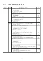
11-2-3 Trouble shooting (Erroneous thread cut)
Trouble Factor Cause of trouble and measure
Page
Erroneous
Mechanical
11. Check the needle bar moves up and down during thread cut.
thread cut 11-1 Adjust position of jump device.
3-2-7
(E-190)
11-2 Replace needle bar cushion.
3-3-7
(E-193)
11-3 Replace needle bar driver.
3-2-6
12. Is position of keeper proper?
12-1 Adjust the fixed position regularly.
3-6-8
13. Check the movement of keeper goes smoothly.
13-1 Readjust if it is not smooth.
3-6-7
Operator 1. No negligence in cleaning thread cut device?
(23-2)
1-1 Tell to clean regularly.
# It's desirable to prepare brush with soft hair and air gun.
2. Is timing of thread tension proper?
2-1 <Upper thread> Considering sewing finish, set tension.
(8-1)
2-2 <Bobbin thread> Considering upper thread tension, set tension.
(4-5)
Environment
1. Are power and voltage rated and stable?
1-1 Supply rated voltage. (23-1)
Thread &
1. Is twist of thread too strong?
cloth
1-1 Use thread with proper twist. 3-1-3
2. No skipping by use of lots of paste?
2-1 Use small amount of paste.
2-2 Remove paste stuck to needle.
( ) ----- Reference instruction book
Summary of Contents for HCD2-1501-40
Page 1: ...Maintenance Manual for Embroidery Machine HCD2 1501 40 Version 2 3 HappyJapan Inc ...
Page 10: ...10 HSA90311 Shell alvania EP Grease2 100g Page 31 33 36 M0404342 Needle height gauge Page 52 ...
Page 150: ...143 10 1 Electrical connection diagram before Rev A for LCD CE board 1 3 ...
Page 151: ...144 10 1 Electrical connection diagram before Rev A for LCD CE board 2 3 ...
Page 152: ...145 10 1 Electrical connection diagram before Rev A for LCD CE board 3 3 ...
Page 153: ...146 10 2 Electrical connection diagram before Rev A for LCD CE U LCD CE MX board 1 4 ...
Page 154: ...147 10 2 Electrical connection diagram before Rev A for LCD CE U LCD CE MX board 2 4 ...
Page 155: ...148 10 2 Electrical connection diagram before Rev A for LCD CE U LCD CE MX board 3 4 ...
Page 156: ...149 10 2 Electrical connection diagram before Rev A for LCD CE U LCD CE MX board 4 4 ...
Page 157: ...149a 10 2a Electrical connection diagram Rev A 1 4 ...
Page 158: ...149b 10 2a Electrical connection diagram Rev A 2 4 ...
Page 159: ...149c 10 2a Electrical connection diagram Rev A 3 4 ...
Page 160: ...149d 10 2a Electrical connection diagram Rev A 4 4 ...
Page 161: ...150 10 3 Connection of inverter Inverter set Inverter set ...
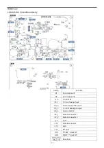
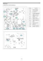
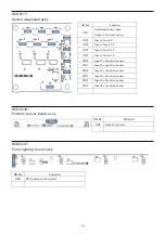
Page 165: ...153 HCD8116 TP SW Circuit Board Ass y HCD8124 TC8 7 Circuit Board Ass y Rev A ...
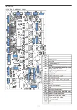
Page 166: ...154 HCD8119 y ...

