13
3b
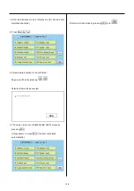
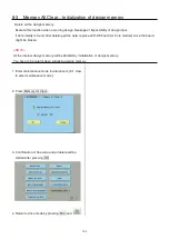
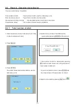
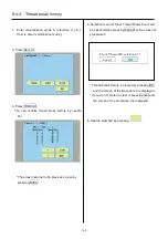
8-8 Machine Setting Navigation after exchanging CONT board (Main program Ver.*1.34~)
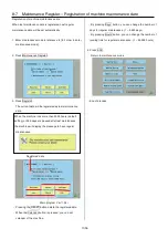
After exchange CONT board, please activate [Machine
Setting Navigation after exchanging CONT board] function.
Then you can set necessary machine setting with one
process.
8-5 Setup Machine setting
7-2 Machine program update
7-3a Main program update
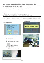
8-6 Position Registration of coordinates for
positioning sensor
7-4
I
nitializing of machine speed
・
Refer to [7-1 Preparation for program update] and prepare
latest update programs.
1.
Insert USB memory that contains data for
version up into insertion slot on the control box.
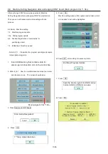
2. Refer to [8-1 How to enter Maintenance mode]
and enter
maintenance mode. The screen shows below:
Main program Ver.*1.34~
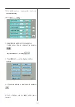
3. Press Replaced CONT Board.
4
.
Press OK
.
5
.
Press OK
.
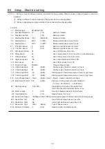
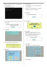
Machine setting menu will be opened and all items which
are required to set will be highlighted.
6. Press ESC after setting of necessary items.
7
.
Press OK
.
8. Press OK
.
Start Setup-Navigation?
Cancel
OK
1
st
Step: Option Selection
OK
2nd Step: Program Update
OK
Save the latest program to USB memory
And set USB to USB slot on panel.
OK
Summary of Contents for HCD2-1501-40
Page 1: ...Maintenance Manual for Embroidery Machine HCD2 1501 40 Version 2 3 HappyJapan Inc ...
Page 10: ...10 HSA90311 Shell alvania EP Grease2 100g Page 31 33 36 M0404342 Needle height gauge Page 52 ...
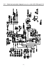
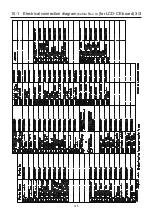
Page 150: ...143 10 1 Electrical connection diagram before Rev A for LCD CE board 1 3 ...
Page 151: ...144 10 1 Electrical connection diagram before Rev A for LCD CE board 2 3 ...
Page 152: ...145 10 1 Electrical connection diagram before Rev A for LCD CE board 3 3 ...
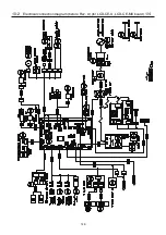
Page 153: ...146 10 2 Electrical connection diagram before Rev A for LCD CE U LCD CE MX board 1 4 ...
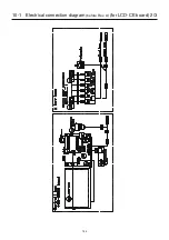
Page 154: ...147 10 2 Electrical connection diagram before Rev A for LCD CE U LCD CE MX board 2 4 ...
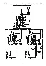
Page 155: ...148 10 2 Electrical connection diagram before Rev A for LCD CE U LCD CE MX board 3 4 ...
Page 156: ...149 10 2 Electrical connection diagram before Rev A for LCD CE U LCD CE MX board 4 4 ...
Page 157: ...149a 10 2a Electrical connection diagram Rev A 1 4 ...
Page 158: ...149b 10 2a Electrical connection diagram Rev A 2 4 ...
Page 159: ...149c 10 2a Electrical connection diagram Rev A 3 4 ...
Page 160: ...149d 10 2a Electrical connection diagram Rev A 4 4 ...
Page 161: ...150 10 3 Connection of inverter Inverter set Inverter set ...
Page 165: ...153 HCD8116 TP SW Circuit Board Ass y HCD8124 TC8 7 Circuit Board Ass y Rev A ...
Page 166: ...154 HCD8119 y ...


