132
8-6 Position Registration of coordinates for positioning sensor
This procedure is to memorize embroidery area into the machine.
This procedure has to be done after exchange of CONT-S2 board, position sensor board etc.
(Machine will display error [ E-67 Position data ] without the registration of coordinate of Position sensor.
<NOTE>
* Registration should be done with outer cover installed.
Correction position may not be registered if the registration is done without the cover.
* As frame moves at maximum embroidery area, be sure not to have anything around the machine.
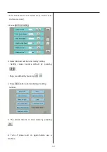
1. Enter maintenance mode in reference to [ 9-1 How to enter
maintenance mode]
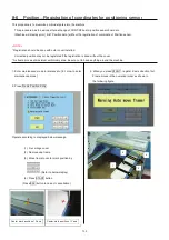
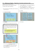
2. Press Frame Position Entry .
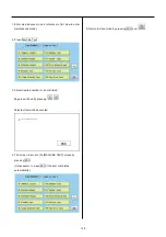
Operate according to displayed below message.
(1). Fix carriage cover
(2). Remove cap frame
(3). Move frame to center mark position by
. (Refer to below display)
(4). Press START button
(Press ESC button in case of cancellation)
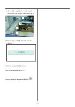
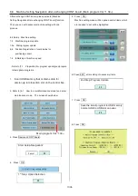
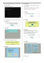
3. When you press START , register X axis direction first.
Frame moves in the numerical order as shown in
the following figure.
Center mark position of X axis
Center mark position of Y axis
1
3
4
2
Summary of Contents for HCD2-1501-40
Page 1: ...Maintenance Manual for Embroidery Machine HCD2 1501 40 Version 2 3 HappyJapan Inc ...
Page 10: ...10 HSA90311 Shell alvania EP Grease2 100g Page 31 33 36 M0404342 Needle height gauge Page 52 ...
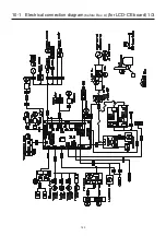
Page 150: ...143 10 1 Electrical connection diagram before Rev A for LCD CE board 1 3 ...
Page 151: ...144 10 1 Electrical connection diagram before Rev A for LCD CE board 2 3 ...
Page 152: ...145 10 1 Electrical connection diagram before Rev A for LCD CE board 3 3 ...
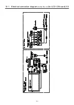
Page 153: ...146 10 2 Electrical connection diagram before Rev A for LCD CE U LCD CE MX board 1 4 ...
Page 154: ...147 10 2 Electrical connection diagram before Rev A for LCD CE U LCD CE MX board 2 4 ...
Page 155: ...148 10 2 Electrical connection diagram before Rev A for LCD CE U LCD CE MX board 3 4 ...
Page 156: ...149 10 2 Electrical connection diagram before Rev A for LCD CE U LCD CE MX board 4 4 ...
Page 157: ...149a 10 2a Electrical connection diagram Rev A 1 4 ...
Page 158: ...149b 10 2a Electrical connection diagram Rev A 2 4 ...
Page 159: ...149c 10 2a Electrical connection diagram Rev A 3 4 ...
Page 160: ...149d 10 2a Electrical connection diagram Rev A 4 4 ...
Page 161: ...150 10 3 Connection of inverter Inverter set Inverter set ...
Page 165: ...153 HCD8116 TP SW Circuit Board Ass y HCD8124 TC8 7 Circuit Board Ass y Rev A ...
Page 166: ...154 HCD8119 y ...


