161
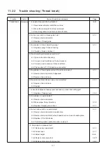
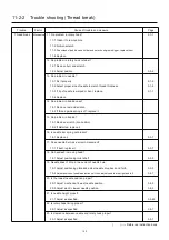
11-2-2 Trouble shooting (Thread break)
Trouble Factor Cause of trouble and measure Page
Thread break
Mechanical
24. Check tip of keeper hit the bobbin case.
24-1 Adjust it regularly. 3-6-8
25. ls take-up lever timing proper ?
25-1 Adjust as specified.
3-2-9
26. No problem in timing belt?
26-1 Adjust tension.
3-8-1
26-2 If scratched or damaged, replace it.
3-8-2
27. Is revolution setting proper?
27-1 Make automatic speed setting.
7-4
28. Is inverter setting proper ?
28-1 Make setting.
6-2
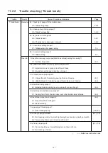
Operator 1. Operation is wrong (no proper [Machine settings] setting for sewing?)
1-1 Tell how to operate.
(5-1)
2.Is pattern dwindled too much by pattern adjustment?
2-1 Adjust size so as to produce less thread break.
2-2 Use pattern edited again (density_ change).
3. Is thread tension properly set?
3-1 <Upper thread> Considering sewing finish, set tension.
(8-1)
3-2 <Bobbin thread> Considering upper thread tension, set tension.
(4-5)
4. Is bobbin winding proper?
4-1 Adjusting bobbin winding tension, wind with proper strength. (4-4)
5. Is bobbin put in bobbin case properly?
5-1 Viewing from front of bobbin case, set so that bobbin turns left-wise.
(4-5)
6. Does thread cone stand properly?
(4-6)
6-1 Keep thread from hitting felt.
6-2 Stand vertically.
7. Is passing of thread proper?
7-1 Pass thread properly.
(4-6) (4-7)
8. Is cloth properly stretched? (6-2) (7-5)
8-1 No loosening and no too much tightening. Even tension in depth and width.
8-2 Texture should be even in direction of X and Y.
9. Is frame properly set?
(6-3) (7-6)
9-1 Frame should be put in positioning hole on tubular-frame.
9-2 No loosening of screw.
( ) ----- Reference instruction book
Summary of Contents for HCD2-1501-40
Page 1: ...Maintenance Manual for Embroidery Machine HCD2 1501 40 Version 2 3 HappyJapan Inc ...
Page 10: ...10 HSA90311 Shell alvania EP Grease2 100g Page 31 33 36 M0404342 Needle height gauge Page 52 ...
Page 150: ...143 10 1 Electrical connection diagram before Rev A for LCD CE board 1 3 ...
Page 151: ...144 10 1 Electrical connection diagram before Rev A for LCD CE board 2 3 ...
Page 152: ...145 10 1 Electrical connection diagram before Rev A for LCD CE board 3 3 ...
Page 153: ...146 10 2 Electrical connection diagram before Rev A for LCD CE U LCD CE MX board 1 4 ...
Page 154: ...147 10 2 Electrical connection diagram before Rev A for LCD CE U LCD CE MX board 2 4 ...
Page 155: ...148 10 2 Electrical connection diagram before Rev A for LCD CE U LCD CE MX board 3 4 ...
Page 156: ...149 10 2 Electrical connection diagram before Rev A for LCD CE U LCD CE MX board 4 4 ...
Page 157: ...149a 10 2a Electrical connection diagram Rev A 1 4 ...
Page 158: ...149b 10 2a Electrical connection diagram Rev A 2 4 ...
Page 159: ...149c 10 2a Electrical connection diagram Rev A 3 4 ...
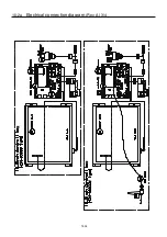
Page 160: ...149d 10 2a Electrical connection diagram Rev A 4 4 ...
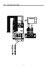
Page 161: ...150 10 3 Connection of inverter Inverter set Inverter set ...
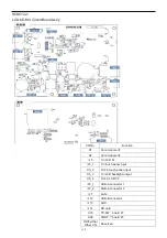
Page 165: ...153 HCD8116 TP SW Circuit Board Ass y HCD8124 TC8 7 Circuit Board Ass y Rev A ...
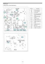
Page 166: ...154 HCD8119 y ...

