Hanwha Techwin Wisenet TNM-C4950TD User Manual Download Page 19

English _

19


!

NETWORK CONNECTION AND SETUP

network connection and setup

You can set up the network settings according to your network configurations.

CONNECTING THE CAMERA DIRECTLY TO LOCAL AREA NETWORK

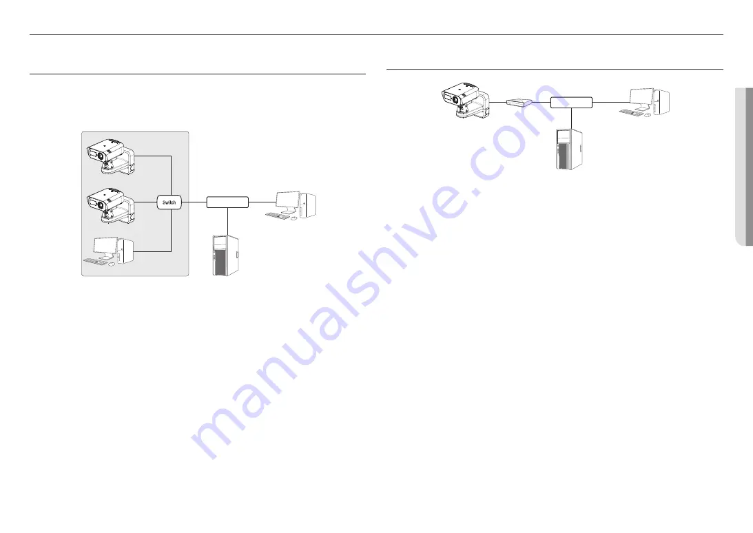
Connecting to the camera from a local PC in the LAN

1. 

Launch an Internet browser on the local PC.

2. 

Enter the IP address of the camera in the address bar of the browser.


M


`

A remote PC in an external Internet out of the LAN network may not be able to connect to the camera installed in the intranet 
if the port-forwarding is not properly set or a firewall is set. 
In this case, contact your network administrator.


`

By factory default, the IP address will be assigned from the DHCP server automatically. 
If there is no DHCP server available, the IP address will be set to 192.168.1.100. 
To change the IP address, use the Device Manager. 
For how to use the device manager, refer to “

USING DEVICE MANAGER

”. (Page 20)

CONNECTING THE CAMERA DIRECTLY TO A DHCP BASED DSL/CABLE 
MODEM

1. 

Connect the user PC directly with the network camera.

2. 

The IP address of the camera can be changed by the Device Manager so that a user can access it on the 
web browser through the Internet.

3. 

Access the Web Viewer of the camera using an Internet browser.

4. 

Move to [

Setup

] page.

5. 

Move to [

Network

] – [

DDNS

] and configure the DDNS settings.

6. 

Move to [

Basic

] – [

IP & Port

], and set the IP type to [

DHCP

].

7. 

Connect the camera, which was removed from your PC, directly to the modem.

8. 

Restart the camera.


M


`

For information on how to set DDNS, refer to the online help of Web Viewer.


`

For information on how to set the IP, refer to the online help of Web Viewer.

Camera

External Remote PC

DDNS Server 
(Data Center, KOREA)

DSL/Cable Modem

INTERNET

Camera

Camera

Local PC

INTERNET

External Remote PC

DDNS Server 
(Data Center, KOREA)

<Local Network>

Summary of Contents for Wisenet TNM-C4950TD

Page 1: ...THERMAL NETWORK CAMERA User Manual TNM C4940TD TNM C4950TD TNM C4960TD...

Page 2: ...ectness of the contents in this document but no formal guarantee shall be provided Use of this document and the subsequent results shall be entirely on the user s own responsibility Hanwha Vision rese...

Page 3: ...non compliant tools the product may be damaged 19 Do not install the product in a place where chemical substances or oil mist exists or may be generated As edible oils such as soybean oil may damage o...

Page 4: ...UL60950 1 or PS2 as defined in UL62368 1 Unit is intended for installation in a Network Environment 0 as defined in IEC TR 62102 As such associated Ethernet wiring shall be limited to inside the buil...

Page 5: ...SETUP 19 19 Connecting the Camera Directly to Local Area Network 19 Connecting the Camera Directly to a DHCP Based DSL Cable Modem 20 Using Device Manager 20 Searching Camera Automatically 20 Configu...

Page 6: ...rs SanDisk Transcend Samsung Product Type High endurance Pro endurance The compatibility varies depending on the card manufacturers and types RECOMMENDED NAS SPECIFICATIONS Recommended capacity 200GB...

Page 7: ...embling a wall mount Anchor bolt 4 Used when fixing a mount plate to a wall AT A GLANCE Appearance b c a Item Description a Wall mount Used when installing a camera on a wall or pillar There is also a...

Page 8: ...Tele W Zoom out Wide N Focus on a near object Near F Focus on a far object Far AF Press this button for automatic focus control b MICRO USB port Port to connect the WiFi dongle You can check the insta...

Page 9: ...Forcing assembly using non standard tools may damage the product Disassembling 1 Separate it by loosening the fastening bolt at the bottom of the wall mount by turning it counterclockwise using the su...

Page 10: ...engraved should face the wall Also install the product so that the arrow in front where TOP POLE is engraved faces the top as shown in the figure When installing the camera on a pillar connect it to...

Page 11: ...wn in the figure 3 4 Connect the network cable s connector to the PoE connection terminal Installation of the Power DC 12V Audio Alarm cable 4 1 Insert the cable bushings of the provided power audio a...

Page 12: ...the power terminal block paying attention to the polarity by referring to the imprint when connecting it 4 4 Insert the power terminal block into the power input terminal DC 12V Installation wall moun...

Page 13: ...the bottom of the camera 2x TR20 2 Insert a Micro SD card in the direction of the arrow J The Micro SD card should be inserted before installing the camera and inputing power source Do not insert it...

Page 14: ...ed CONNECTING WITH OTHER DEVICE Grounding cable Wi Fi dongle Power PoE Router J The Micro USB port is used to connect a Wi Fi dongle to communicate a smartphone installed the applications Smartphone v...

Page 15: ...IS WF2123 n300 EDIMAX EW 7811Un V2 New ver IP Time N100mini IP Time N105L TP LINK TL WN823N V1 TP LINK TL WN725N TP LINK T2U Nano ASUS USB N13 ASUS USB N10 NANO NETGEAR WNA3100M IODATA WN G150UMW IODA...

Page 16: ...thermal imaging screen will require about 30 minutes for stabilizing as it is being continuously calibrated If you want to connect an external device you must turn it off before doing it Before connec...

Page 17: ...output 1Vrms Line out impedance 600 J In the case you access the web viewer and select an external microphone as the audio input sources in Video Audio Audio setup the following specifications are rec...

Page 18: ...and current specifications are connected by using the open collector method it may cause malfunction Refer to the Alarm Out Wiring Diagram when connecting devices such as a warning lamp or a siren Sen...

Page 19: ...ge the IP address use the Device Manager For how to use the device manager refer to USING DEVICE MANAGER Page 20 CONNECTING THE CAMERA DIRECTLY TO A DHCP BASED DSL CABLE MODEM 1 Connect the user PC di...

Page 20: ...nistrator HTTP Port Used to access the camera using the Internet browser The default value is 80 RTSP Port Used to control real time streaming The default value is 554 If using a Broadband Router IP A...

Page 21: ...STERING CAMERA MANUALLY If the camera cannot be found using search function the camera can be registered remotely by manually inserting IP information if the camera is connected to external network 1...

Page 22: ...arding setting is an example of setting a CISCO IP router The settings may differ depending on the connected Broadband Router model For more information refer to the user manual of the applicable rout...

Page 23: ...A THE INTERNET On a remote computer that is in the Broadband Router s network cluster users can access cameras within a Broadband Router s network by using the camera s DDNS URL 1 Before you can acces...

Page 24: ...ting system to support the UPnP protocol 2 Click the camera name for search In the Windows operating system click the camera name searched from the network menu The login window is displayed Connectin...

Page 25: ...se your password by using a memo pad or memorizing it LOGIN Whenever you access the camera the login window appears Enter the User ID and password to access the camera 1 Enter admin in the User name i...

Page 26: ...M SOLUTION Motion detection of Analytics is set to Enable but no notification e mail reaches me even when an analysis event had occurred Verify the settings in the following sequence A Check Data Time...

Page 27: ...f where and how they can take these items for environmentally safe recycling Business users should contact their supplier and check the terms and conditions of the purchase contract This product and i...

Page 28: ......

Reviews: