9
APM-001e
AUG 2015
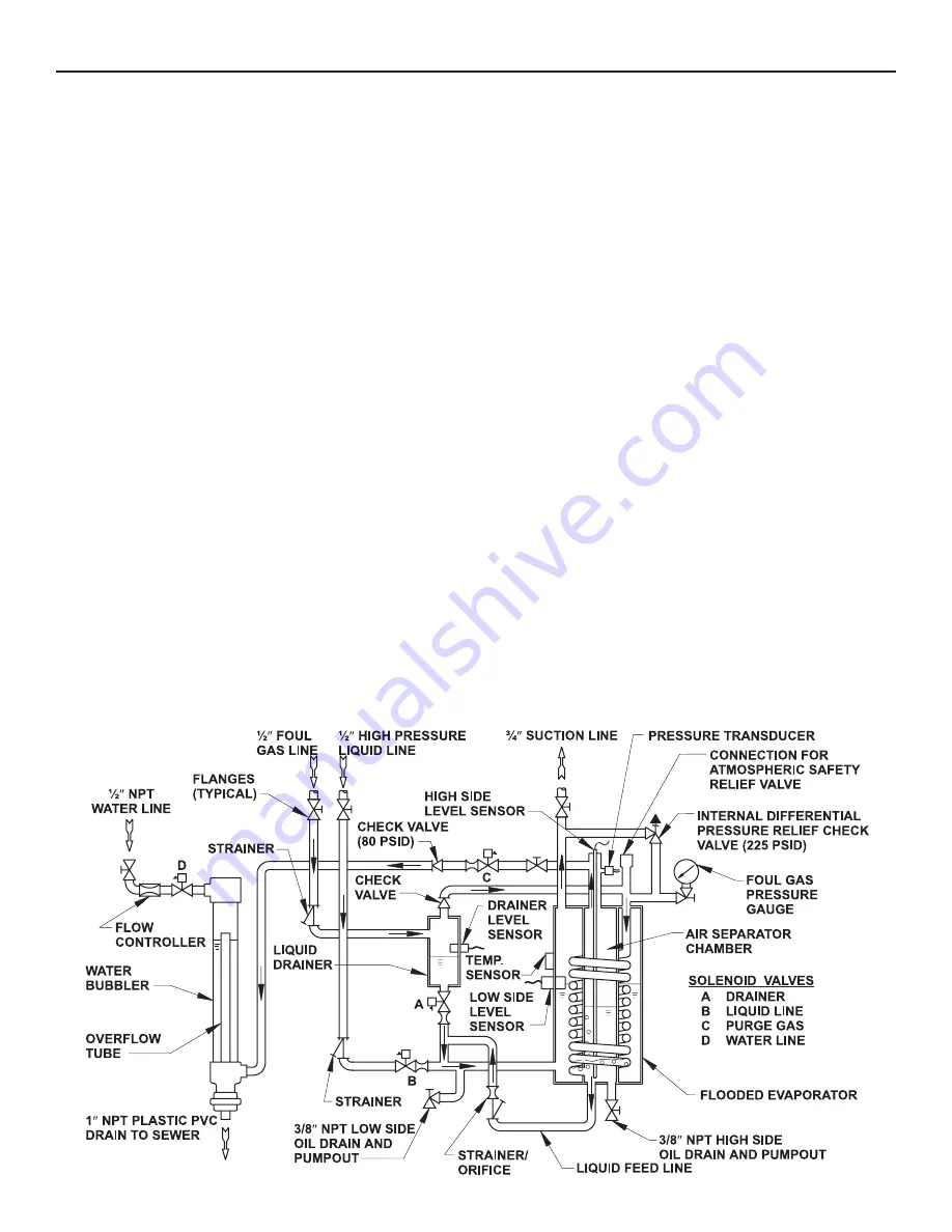
The APM is designed to automatically start-up and operate
without the assistance of plant personnel. Beginning at
start-up, the following is a description of the refrigerant
flow through a purger.
Keep the control cabinet door closed at all times to
prevent water damage and tampering.
PURGER START-UP SEQUENCE
On start-up, liquid refrigerant fills and begins to cool the
purger. The liquid line solenoid valve (B) energizes to
feed refrigerant to the flooded evaporator. The low side
level sensor, located on the side of the flooded evaporator,
senses when liquid reaches the proper level. The display
should show 3333.
At the same time the flooded evaporator is filling, foul
gas enters the flooded evaporator condensing coil and
the refrigerant gas contained therein changes state to a
liquid. The liquid and noncondensible gas gradually fill
the air separator chamber.
As the purger continues to cool down, a temperature sensor
attached to the flooded evaporator senses temperature.
At approximately 40°F (4.4°C) evaporator temperature, the
readout will no longer display 3333 and the purger will
enter the mode selected.
Foul gas is continually processed as long as a remote
purge point solenoid is energized. It is important that
one, but only one, remote purge point solenoid valve is
open at all times to prevent losing foul gas pressure to the
purger. If foul gas pressure is lost (as sensed by pressure
transducer), diagnostic code 2222 flashes on the APM
digital readout. No purging of air will occur until foul gas
pressure is restored.
OPERATION
The foul gas may carry a certain amount of condensed
refrigerant which is captured by the liquid drainer before
it enters the flooded evaporator coil of the purger. The
drainer level sensor operates solenoid valve (A) to drain
the liquid directly into the low-pressure flooded evaporator.
This separation step enables the liquid refrigerant to bypass
the purger’s flooded evaporator condensing coil.
The liquid-free foul gas enters the condensing coil, which
is submerged in the cold liquid refrigerant of the flooded
evaporator. The refrigerant gas condenses while the
noncondensible gas passes into the air separator chamber.
The condensed liquid refrigerant is removed from the air
separator chamber through the strainer with integral orifice,
and passed into the low-pressure side of the flooded
evaporator.
Meanwhile, the noncondensible gas collects in the air
separator chamber. The collected noncondensible gas
gradually depresses the liquid level causing the high side
level sensor to open both the purge gas solenoid valve
(C) and water solenoid valve (D). Inside the water bubbler,
noncondensible gas and water mix so that residual amounts
of ammonia can be absorbed. The waste water is flushed
to the drain through the overflow tube.
The purger will cycle each enabled remote purge point
solenoid valve in sequence, when the purger is on Automatic
Operation or New System Start-up. The Purger will remain
at the selected purge point when in Manual Operation.
SECTION 3 APM OPERATION
Figure 11


