


7
APM-001e
AUG 2015
ACTIVE PURGE POINT
The front of the control cabinet has lights which indicate
the active purge point. The active purge point can be
manually advanced in any operational mode by pushing
the purge point advance button.
PURGER STATUS LIGHTS
There are two purger status lights on the front of the control
cabinet next to the digital readout. These are the Purging
status light and Standby status light which indicate when
noncondensible gas (air) is being released from the purger
(Purging), or when the purger is in a waiting mode (Standby).
PURGING LOG
The purging log is displayed on the digital readout. It
displays the number of minutes the purge gas solenoid valve
(C) (see Figure 11) has been open to release noncondensibles
into the water bubbler.
The purger log can be used to track the release of
noncondensible gas. If a daily or weekly record is kept, then
any abnormal increases in the amount of noncondensible
gases can be noted, and corrective measures can be taken.
Little or no activity compared to normal operation may
indicate noncondensibles have been thoroughly removed
or a problem with the purger. Frequent activity beyond
normal could mean excessive new leakage of air into the
system. To reset the purge log, push the zero reset button
next to the digital readout on the front panel.
DIAGNOSTIC FEATURES
Although the APM is very reliable, after an extended
operation or under severe conditions, problems may
occur or be suspected. Under these conditions, due to
the importance of the purging functions, restoration to
normal operation is desired as quickly as possible. The
APM features diagnostic codes which are displayed on the
digital readout when abnormal operation of the refrigeration
system or the APM is detected. These flashing numbers
help to identify the problem area. Below is a quick reference
to these diagnostic codes. The digital readout will display
the diagnostic code related to the occurrence which first
put the APM into this mode; exception, 6666 will override
7777. Also see the troubleshooting guide on page 10 for
detailed explanation.
Flashing 2222 LOSS OF FOUL GAS PRESSURE.
Flashing 3333 PURGER TOO WARM.
Flashing 4444 PURGED OVER 60 MINUTE TIME LIMIT.
Flashing 5555 PURGER SHUT-OFF REMOTELY.
Flashing 6666 LEVEL CONTROL OUT OF RANGE.
Flashing 7777 LOSS OF HIGH-PRESSURE LIQUID.
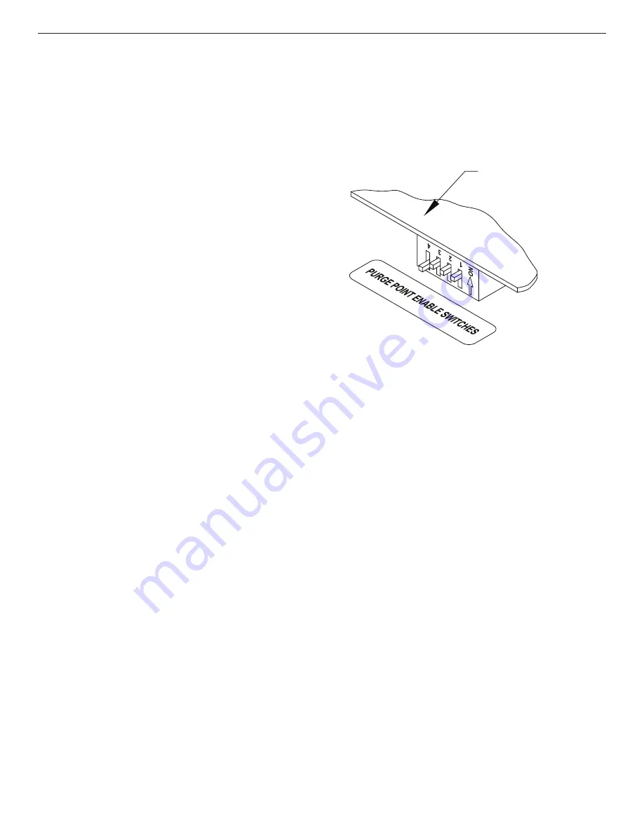
PURGE POINT ENABLE SWITCHES
These switches are located on the control board and are
all factory-set to the ON position. They control whether
or not a purge point can become active. If for example,
only three purge points are being utilized, the number 4
purge point enable switch should be in the downward off
position (see Figure 7). By doing this, the unused purge
point is disabled and purger time is not wasted.
PUMP OUT PROCEDURE
Performing certain types of service on the APM may first
require the purger to be pumped-out (drained of liquid
refrigerant). To begin pump-out, shut off the foul gas
and high-pressure liquid lines. Wait for all refrigerant to
evaporate to suction; this usually takes several hours to
complete. Using safe refrigeration practices, reduce the
pressure to zero. In addition to following these procedures,
check the lower portion of drainer and the APM piping for
signs of frost. If there is no frost, pump-out is probably
complete. If there is frost, this means excess refrigerant
is still in the drainer and/or piping. To drain, energize the
drainer solenoid valve.
To accelerate the pump out process, attach ammonia hoses
to the oil drain valves. Close the main suction line to the
purger. Using the oil drain valves, pump out to a lower
suction pressure than the main purger suction line. When
pumped out, close the oil drain valves and leave the main
suction line closed to isolate the purger. With electricity
on, the pressure in the purger should remain at zero. This
process should be completed only by knowledgeable
refrigeration technicians.
CONTROL BOARD
Figure 7
SECTION 2 ELECTRICAL INSTALLATION & OPERATION


