RC2-D Technical Manual
39
When the compressor is running, the copper pipe can reduce the vibration. If steel pipe is necessary,
proper welding is very important to avoid stress in the pipeline system. These internal stresses will
cause resonance and noise, which will reduce the life-time of the compressor.
3)
The oxidation impurities and debris in the pipeline due to welding should be removed. If these
impurities enter into the compressor, the oil filter may be blocked, and the lubrication system and the
capacity-control system may be invalid.
4)
The material of suction and discharge flange is steel, which can be directly welded with pipeline.
After welding, it should be cooled in the atmosphere and is forbidden to use water for cooling.
8.1.4
Angle limit of compressor installation
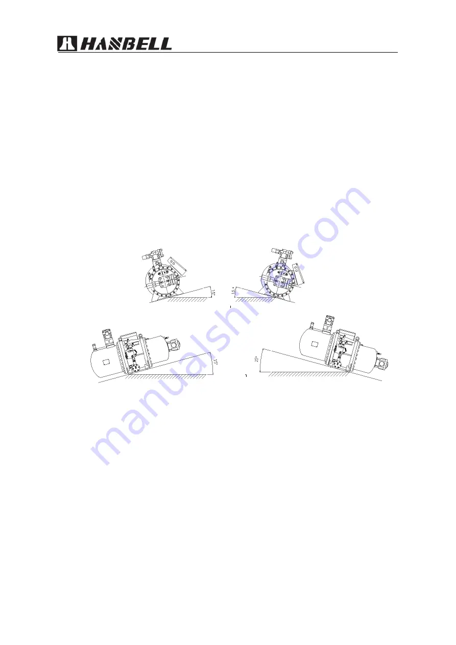
Below picture shows the maximum inclination angle when the compressor is installed. If the
inclination angle is bigger than the limit value, the oil level will be too low which causes the
compressor to stop. However, in some special applications, the inclination may exceed the limit. For
example, when it is used on the ship, it is recommended to have an external oil separator and
associated auxiliary components. Please contact Hanbell for further installation instructions.
Inclination angle of compressor installation
8.1.5
Ambient temperature
The ambient temperature shall be between -15
℃
and +50
℃
.
8.1.6
Suction superheat
R22
:
5
~
10 K
R507A/R404A
:
5
~
10 K (Recommended minimum 8 K)
Note:
suction superheat is the difference between suction temperature and dew-point
temperature under evaporation pressure.
8.1.7
Design pressure
Maximum working pressure: low/high pressure: 12.5 / 25 bar
In order to prevent the compressor from operating beyond the limit allowable range, it is necessary
to install high pressure and low pressure switch.
The design and test of the compressor conform to Chinese national standard GB/T 19410.
Summary of Contents for RC2-D
Page 27: ...RC2 D Technical Manual 2 RC2 200 470 D S P terminal box 3 RC2 510 930 D S P terminal box ...
Page 45: ...RC2 D Technical Manual 47 RC2 180D S Drawing ...
Page 46: ...RC2 D Technical Manual 48 RC2 200 620D S Horizontal suction port Drawing ...
Page 48: ...RC2 D Technical Manual 50 RC2 620 930D S Vertical suction port Drawing ...
Page 49: ...RC2 D Technical Manual 51 10 2 RC2 100 930D P Drawing RC2 100 140D P Drawing ...
Page 50: ...RC2 D Technical Manual 52 RC2 180D P Drawing ...
Page 51: ...RC2 D Technical Manual 53 RC2 200 620D P Drawing ...
Page 53: ...RC2 D Technical Manual 55 RC2 620 930D P Drawing ...


