45
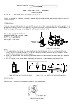
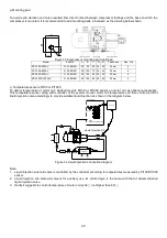
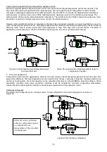
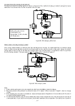
j. Liquid injection system (solenoid valve + stop valve)
This simple liquid injection system adjusts amount of liquid
injection by stop valve, suitable for application with level load
and ambient temperature but it’s not recommended. Opening
ratio of stop valve is fix even system loading and
motor/discharge temperature change. Therefore, frequent
check of discharge temperature can prevent damage of
compressor due to over cooling or insufficient cooling.
Figure 26 Liquid injection – solenoid valve + stop valve
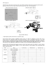
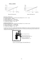
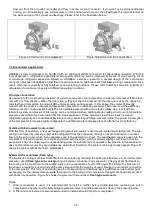
k. Horizontal check valve
Horizontal check valve is a standard accessory of compressors for flooded system. Please refer to section C. for
dimension of horizontal check valve. A sample installation is shown below:
Gasket
Check valve
Length
Gasket
Stop valve
Figure 27 Dimensions and installation of horizontal check valve
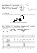
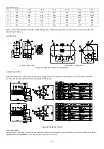
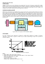
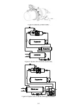
l. External oil separator
For improvement of oil return in flooded-type, low-temperature and parallel systems, system with long piping, Hanbell
specially designs a complete series of external oil separators – OS series with characteristics of high separation
efficiency and low pressure drop. The following table shows details of OS series:
(
) Technical data
Ⅰ
:
Model
Type
Oil Volume (Liter)
Range of application based on Displacement (m
3
/hr)
(Recommended)
Shell Diameter
High level
Low level
OS40
Vertical
17
9
205
14”
OS50
Vertical
22
12
206~270
16”
OS65
Vertical
31
18
271~440
18”
OS80
Horizontal
33
20
441~705
20”
OS100
Horizontal
40
27
706~1120
20”
OS125
Horizontal
50
30
1121~1310
24”
OS150
Horizontal
60
36
1311~1835
24”
(
) Accessories
Ⅱ
:
No.
Description
OS40
OS50
OS65
OS80
OS100
OS125
OS150
1
Refrigerant inlet
1 1/2”
2”
2 1/2”
3”
4”
5”
6”
2
Refrigerant outlet
1 1/2”
2”
2 1/2”
3”
4”
5”
6”
3
Oil outlet
5/8” Flare
5/8” Flare
5/8” Flare
1” PF
1” PF
1 1/4” PF
1 1/4” PF
4
Oil charge valve
1/4” Flare
5
High oil S.G.
1 PCS
6
Low oil S.G.
1 PCS
7
Oil level switch
1 PCS
8
Oil heater
150W
150W
150W
150W
150W
300W
300W
9
Oil drain valve
1/4” Flare
10
Oil temp. protection (option)
1/8” NPTF
11
Safety valve (option)
1/2”
1/2”
1/2”
1”
1”
1 1/2”
1 1/2”
Summary of Contents for RC2-AV Series
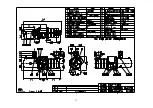
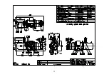
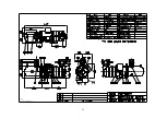
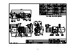
Page 15: ...4 3 RC2 AV series compressor outline drawings...
Page 16: ...15...
Page 17: ...16 UNIT SI mm Imperial in...
Page 18: ...17...
Page 19: ...18...
Page 20: ...19...
Page 21: ...20...
Page 22: ...21...
Page 23: ...22...
Page 24: ...23...
Page 25: ...24...
Page 26: ...25...
Page 27: ...26...
Page 28: ...27...
Page 29: ...28...
Page 30: ...29...
Page 31: ...30...
Page 32: ...31...
Page 33: ...32...
Page 34: ...33 SI mm Imperial in UNIT...
Page 35: ...34...
Page 36: ...35...
Page 37: ...36...

