7
Double-walled rotor housing- Double casing structure with high strength inner ribs has been designed to minimize
noise and ensure rigidity. The rotor housing is made of high-strength gray cast iron FC25 that is extremely stable,
therefore no expansion will occur even at high-pressure condition. These casings are machined by computer aided
machining centers and inspected by precision measuring machines to enhance reliability.
Direct flange-on oil separator- A vessel made of ductile material FC 500 specially designed to withstand high
pressure and provide the highest efficiency of oil separation. Simple oil management, three-staged oil separator, low-
pressure-drop demister to ensure the minimum refrigerant dilution in the oil and maintain high oil viscosity.
Precise capacity control- Instead of slide valve, RC2-V series screw compressors modulate capacity by varying
rotation speed of motor rotor between 20 and 80(60) Hz.
Perceptive protection modules- RC2-V series screw compressors are equipped with PTC thermistors and motor
protection module which could monitor discharge and motor coil temperature. Accessories such as oil level switch to
monitor the level of oil, pressure differential switch, and pressure relief valve are options for specific applications.
Adaptable with additional cooling- Liquid injection connection port located on the motor casing and the compression
casing. There are also oil cooler connectors and economizer connection port to meet application needs.
2.5 Compression process
a. Suction and sealing:
At the beginning of the compression cycle, as the male rotor and female rotor unmesh, gas from suction port fills
the interlobe space (refer to the dark area in Figure 6). Refrigerant at suction pressure continues to fill it, until the
trailing lobe crosses the suction area and the gas is trapped inside the interlobe space.
b. Compression:
As the male rotor and female rotor meshes, the interlobe space moves towards to discharge end and its volume
decreases so that gas pressure increases consequently.
c. Discharge:
Gas is discharged from the interlobe space when the leading lobe crosses the discharge port whose volume ratio is
designed differently for various applications.
Figure 6 Compression process
2.6 Guide to VFD application
When operating RC2-V series screw compressor with frequency inverter (VFD, variable frequency driver), pay
attention to following points:
1. Max rotation frequency must be within nominal rotation frequency of the motor; min rotation frequency should be
20Hz.
2. To run compressors out of working frequency mentioned above, e.g. powering a 380V/3P/70Hz motor between 20
and 80Hz, please consult Hanbell before running. Running at frequency out of designed range will result in lower
efficiency or serious damage to the compressor and motor.
3. Consult your VFD supplier before installation to check if the ambient conditions are proper for the VFD. If
necessary, the VFD should be fully-enclosed for adequate cooling and humidity-control.
4. Consult your VFD supplier to get compatible NFBs for better protection.
5. An AC reactor should be installed between the power supply and the VFD (primary side). The installation of
another AC reactor between the compressor and the VFD (secondary side) is strongly recommended, especially
when the wiring length between the VFD and the motor is longer than 5m. Consult your VFD supplier for reactor
selection and installation.
6. Wiring of chiller controller and compressor protection modules such as PTC thermistors or oil level switch should
be isolated from wiring of the VFD’s power input/output to prevent interference.
7. VFD and compressor must be well-grounded respectively.
8. Use VFD phase loss and phase sequence detecting functions and nullify detection of motor protector INT69HBY to
(A) Suction and sealing
(
B) Compression
(C) Discharge
Summary of Contents for RC2-AV Series
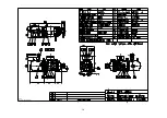
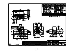
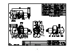
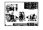
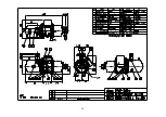
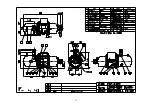
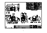
Page 15: ...4 3 RC2 AV series compressor outline drawings...
Page 16: ...15...
Page 17: ...16 UNIT SI mm Imperial in...
Page 18: ...17...
Page 19: ...18...
Page 20: ...19...
Page 21: ...20...
Page 22: ...21...
Page 23: ...22...
Page 24: ...23...
Page 25: ...24...
Page 26: ...25...
Page 27: ...26...
Page 28: ...27...
Page 29: ...28...
Page 30: ...29...
Page 31: ...30...
Page 32: ...31...
Page 33: ...32...
Page 34: ...33 SI mm Imperial in UNIT...
Page 35: ...34...
Page 36: ...35...
Page 37: ...36...


