48
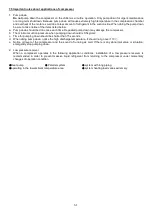
p. Mounting pad
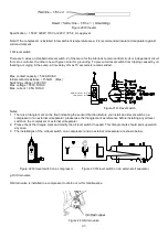
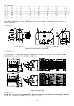
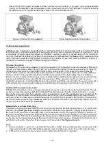
To avoid extra vibration and noise resulted from direct contact between compressor footings and the base on which the
compressor is mounted, it is recommended to add mounting pads in between as the drawing below shown.
E
A
B
C
D
Figure 33 Compressor mounting pad (optional)
Model
Part No.
A
B
C
D
E
Thickness
Req. Q’ty
RC2-100~320AV
3131-9815B
20
55
50 20 22
20 mm
4
RC2-340~580AV
3136-9815B
26 100 70 25 22
20 mm
4
RC2-620~930AV
3139-9815B
25 100 80 25 22
20 mm
4
RC2-1020~1530AV
3142-9815B
40 100 80 40 22
20 mm
4
q. Temperature sensors Pt100 or Pt1000
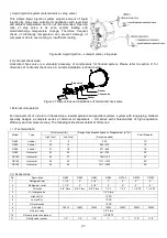
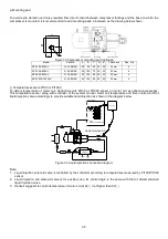
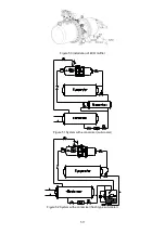
To detect temperature of motor coil, Hanbell mounts Pt100 or Pt1000 sensor on motor coil as optional accessories.
This temperature sensor along with controller of the system monitor motor coil temperature and then control on/off of
liquid injection valve accordingly to provide suitable liquid injection as shown in the diagram below.
s
C
o
n
d
e
n
s
o
r
s
Evaporator
Dryer
Chiller
in
Chiller
out
W
U
Earth Bolt
V
B:Pt100 / Pt1000
Ω
(Optional)
A:PTC
Z
Y
X
B
A
Controller
Electric Plate
Liquid Injection S.V
Figure 34 Liquid injection connection diagram
Note:
1. Liquid injection solenoid valve is controlled by the controller according to temperatures measured by Pt100/Pt1000
sensor.
2. Liquid injection sub solenoid valve is for auxiliary use. Its control logic is the same with that of aforementioned
liquid injection valve.
3. Hanbell suggests to control temperature of motor coil at 60
(not higher than 60
)
℃
℃
Summary of Contents for RC2-AV Series
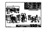
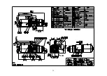
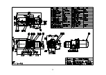
Page 15: ...4 3 RC2 AV series compressor outline drawings...
Page 16: ...15...
Page 17: ...16 UNIT SI mm Imperial in...
Page 18: ...17...
Page 19: ...18...
Page 20: ...19...
Page 21: ...20...
Page 22: ...21...
Page 23: ...22...
Page 24: ...23...
Page 25: ...24...
Page 26: ...25...
Page 27: ...26...
Page 28: ...27...
Page 29: ...28...
Page 30: ...29...
Page 31: ...30...
Page 32: ...31...
Page 33: ...32...
Page 34: ...33 SI mm Imperial in UNIT...
Page 35: ...34...
Page 36: ...35...
Page 37: ...36...

