4
FIG. 2 FIG. 3
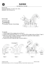
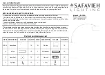
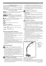
STEP 3:
ELECTRICAL CONNECTIONS
1.
When removing the supply wires from the ceiling outlet box the white supply and green (or bare copper) ground
wire should be on one side of the track and the black supply wire should be on the other.
2.
Connect the white wire (neutral or common) from the supply circuit to the white from the floating live-end
connector. Connect the black (hot) wire from the supply circuit to the black wire from the floating live-end
connector. Connect the green or bare copper ground wire from the supply circuit to the green conductor of the
floating live-end connector. Secure splices with UL Listed wire connectors suitable for the size, type and number
of conductors. (see Figure4.)
3.
Carefully push the leads into the ceiling outlet box. Tighten the toggle bolts and attach the plastic floating live-end
connector canopy with the screws provided.
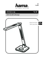
FIG. 4
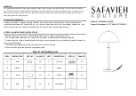
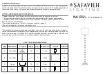
STEP 4:
ATTACH TRACK TO CEILING
Please Note: If you are connecting 2 track sections together start with Point #1(Not provided on all models),otherwise
start with Point#2.
1.
Using the straight connector – IMPORTANT: Determine ground side of track (has indented groove on face and
two internal copper bars) and connector (side of connector with two metal tabs).Can only be assembled if grounds
are aligned.
a. Loosen set screw on end cap at appropriate track ends and remove. Loosen set screws on connector.
b. Aligning the ground sides of the track and connector, push the connector into open ends of track. Tighten set
screws.(see figure 5)
2.
Raise the track assembly to the ceiling. Mark the mounting holes locations with a pencil. Insure the floating live-
end connector body is positioned over the ceiling outlet box.
3.
Drill holes suitable for the fasteners you will be using. Toggle bolts supplied with the track requires 5/8 inches
hole.
4.
Insert the toggle bolts through the holes near the ends of the track. Screw bolts into the toggle wings two or three
turns.
5.
Push toggle bolts into the holes drilled into the ceiling and tighten toggle bolts until the track is about 1/4 inch
from the ceiling. Do not fully tighten toggle bolts until after electrical connections are made.
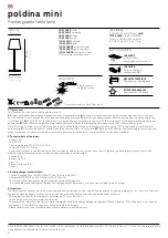
FIG. 5
BLACK
GROUND
WHITE
FLOATING LIVE-END
CONNECTOR
TAB
TRACK SECTION
INDENTATION
MOUNTING PLATE
SCREW
WHITE
BLACK
GREEN
WIRE CONNECTOR
OUTLET BOX
BLACK (HOT)
WHITE (NEUTRAL)
GREEN (GROUND)
MOUNTING PLATE
WHITE
GREEN
BLACK
Set screws
track
Ground conductor
tab on this side
Ground groove side