48
Adjustments and tool changes
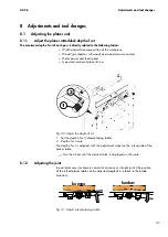
The planer table is set so that with a workpiece length of 1 m, a concave joint of
approximately 0.1 to 0.2 mm is produced (standard setting).
A change by the customer is not foreseen, but can be made by a Felder Group
service technician.
8.1.3
Adjust outfeed planer table
NOTICE
Malfunction due to improper adjustment
When surface planing, workpiece stops when it reaches the out-
feed side of the planer table.
−
The outfeed planer table must lay below the trajectory of the
blades.
−
The setting must be checked with a gauge.
‘Check the setting of the planer table on the outfeed side’
1
2
A
B
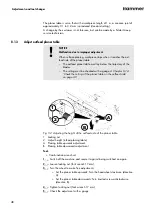
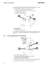
Fig. 32: Adjusting the height of the outfeed side of the planer table
1 Locking nut
2 Adjust height (infeed planing table)
A Planing table upwards adjustment
B Planing table downwards adjustment
Tool:
●
Combination wrench set
1.
Switch off the machine and secure it against being switched on again.
2.
Loosen locking nut (fork wrench 17 mm).
3.
Turn the wheel to make fine adjustments.
●
Set the planer table upwards: Turn the handwheel clockwise (direction
A).
●
Set the planer table downwards: Turn knurled screw anticlockwise
(direction B).
4.
Tighten locking nut (fork wrench 17 mm).
5.
Check the adjustment with a gauge.

