background image

52

Adjustments and tool changes

Open the planer tables and prepare the machine to operate

1.

Release the planer table clamping levers and pull out.

2.

Tilt the infeed planer table up.

3.

Tilt the outfeed planer table up.

4.

Ensure that the safety latch slots correctly into place.

5.

Swing the extraction hood upwards and lock in place.

6.

Connect the extraction hood to the extraction supports.

8.2

Changing over from the thicknesser to the planer

1

2

3

5

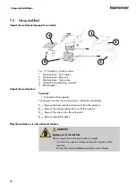
4

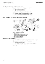
Fig. 37: Preparing to changeover

1 Extraction pipe

2 Thicknesser opening height mind. 150 mm

3 Swing the extraction hood downwards

4 Safety catch (outfeed side)

5 Safety catch (infeed side)

Preparing the machine to changeover

1.

Switch off the machine and secure it against being switched on again.

2.

Remove the extraction hose from the extraction hood.

3.

Adjust the thicknessing height.

🡆

The thicknesser must be at least 150 mm below the cutterblock.

4.

Swing the extraction hood downwards.

Summary of Contents for A2-26

Page 1: ...or future reference Please read this operating manual carefully before using the machine Translation of the original operating instructions A2 26 Planer thicknesser Download your local language http fg am ba manuals CZ ES DE DA EN NL HU FR PL IT SV RO RU 511010 901 1 en_GB ...

Page 2: ... 2022 FELDER KG KR Felder Straße 1 6060 HALL in Tirol AUSTRIA Telephone 43 5223 5850 0 Email info felder group com Internet www felder group com ...

Page 3: ... safety equipment 11 2 7 Residual risks 11 2 7 1 Transport setup installation and disposal 13 2 7 2 Operate 14 2 7 3 Maintain and troubleshoot 15 2 8 Foreseeable misuses 16 3 Declaration of Conformity 18 4 Technical information 20 4 1 Dimensions and weight 20 4 2 Operation and storage conditions 21 4 3 Electrical connection 21 4 4 Drive motor 21 4 5 Planing unit 21 4 6 Dust extraction 22 4 7 Dust ...

Page 4: ...he machine is to be installed 37 7 2 Set up and level 38 7 3 Install 41 7 3 1 Assemble the planer fence 41 7 3 2 Mount the planer fence 43 7 3 3 Mount the cutterblock cover 43 7 3 4 Mount the handwheel 44 7 4 Install the dust extraction 45 7 5 Connect electrics 46 7 5 1 Connect the machine plug 46 8 Adjustments and tool changes 47 8 1 Adjusting the planer unit 47 8 1 1 Adjust the planer cutterbloc...

Page 5: ... 3 Prohibited thickness planing working methods 64 9 4 4 Workpiece dimensions thickness planing 64 9 4 5 Thickness planing 64 10 Maintenance 67 10 1 Maintenance schedule 68 10 2 Cleaning and lubricating 68 10 3 Clean the machine 69 10 4 Preparation Remove the maintenance cover 70 10 5 Transport rollers and kickback guards 71 10 6 Check belt tension and belt condition 72 10 7 Drive chain feed rolle...

Page 6: ...6 Table of contents 12 3 Spare parts list 86 12 4 Circuit diagram 92 ...

Page 7: ...ger which can result in minor or slight injuries if it is not avoided NOTICE indicates a situation of possible danger which can result in material damages if it is not avoided Tips and recommendations emphasises useful tips and recommendations as well as infor mation for efficient and trouble free operation 1 2 Contents of the operating manual This operating manual describes the safe and proper us...

Page 8: ...and images do not necessarily represent the exact product that has been delivered The images and graphics are not depicted on a 1 1 scale The product that has been delivered may have custom built specifications add on options or recent technical modifications and may therefore deviate from the descriptions instructions and images contained in the manual We reserve the right to make technical chang...

Page 9: ...ne must be kept visible readable and may not be removed Pictograms signs and labels that have become damaged or unreadable must be replaced promptly 2 3 Responsibilities of the operator This manual must be kept in the immediate vicinity of the machine The manual must be accessible at all times to all persons working on or with the machine The machine may only be operated if it is in proper working...

Page 10: ...el to work on the machine it is necessary to observe all local regulations regarding age and professional status The machine may only be operated by an adult that is without mental limitations or under the supervision of such a person All operators must ensure that unauthorised persons are kept at a safe dis tance from the machine Personnel are obliged to immediately report any irregularities with...

Page 11: ...ard analysis The design and construction of the machine are based on the results of this analysis and correspond to state of the art technology The machine is considered operationally safe when used properly Even if the safety measures are complied with there are still certain associated risks that must be considered when working on the machine Generally applicable residual risks Crushing by being...

Page 12: ...work around the machine Remove loose objects from the working area Keep the work area orderly and clean Insufficient lighting of the installation room Serious injuries Light installation room sufficiently Standing on the machine The covers or projecting components of the machine are not suitable for standing on them If the machine falls down severe breaks can occur It is forbidden to climb onto th...

Page 13: ...achine may only be set up by authorised trained personnel who are familiar with how to operate the machine and are in strict observance of all safety instructions Before assembling and installing the machine check to make sure it is com plete and in good condition Only assemble and install the machine if the machine and all of the parts are complete and intact Do not setup machine in areas with hi...

Page 14: ...es to ensure good working condition Do not switch off circumvent or remove protective and safety devices during operation Large or small workpieces Serious injuries Ensure that there is sufficient space to work around the machine Drive fed workpieces could be a hazard when processing Keep sufficient distance from walls machines and fixed objects Support long workpieces with additional supports e g...

Page 15: ...and troubleshoot Improper operation of the machine Serious injuries Work on the machine may only be carried out by authorised trained per sonnel who are familiar with how to operate the machine and are in strict observance of all safety instructions If possible only perform work when the machine is disconnected from all energy sources and an unintentional restart is prevented The machine has to be...

Page 16: ...ety devices can not be guaranteed Deficiently maintained safety devices can cause severe injury Safety devices have to be replaced by expert personnel from Felder Group before the end of the lifespan Improper replacement or reparation of safety devices with safety function Serious injuries Only let safety devices be replaced or repaired by expert personnel of the Felder Group Improper correction o...

Page 17: ...sing of workpieces in the same direction as the rotation of the tool Feed direction corresponds to the direction of movement of the cutting edge in the area of contact Maintenance misapplication Service work carried out by untrained or unauthorised personnel Non observance of the maintenance guidelines To ensure quick and unmistakable communication visual contact with the operators must be kept at...

Page 18: ...d 2006 42 EC 2014 30 EC The following harmonised norms were applied EN ISO 19085 1 EN ISO 19085 7 The prototype test was carried out by TESTPLUS TEKNİK KONTROL ve BELGELENDİRME TİC LTD ŞTİ Abdurahmangazi Mh Ebubekir Cad No 34 15 34887 Sancaktepe İstanbul Turkey NB2908 Conformity with the EC Machine Guidelines certified by EG Design Test Certificate number EG Design Test Certificate No 29082209142 ...

Page 19: ...esignation Planer thicknesser Manufacturer Hammer Model type A2 26 The following UK guidelines were applied S I 2008 1597 Supply of Machinery Safety Reg ulations 2008 S I 2016 1091 Electromagnetic Compatibility Reg ulations 2016 The following harmonised norms were applied EN ISO 19085 1 EN ISO 19085 7 This Declaration of Conformity is only valid if the UKCA label is affixed to the machine Modifyin...

Page 20: ... Value Unit Space requirement A x B 690 x 440 mm Total height C Planing 910 mm Total height C1 Thickness planing 1300 mm Total width D min max 970 mm Total length E 1130 mm Net weight 150 kg incl planer fence Packaging dimensions incl pallet Data Value Unit Total height C 800 mm Total width D 560 mm Total length E 1100 mm Net weight 175 kg ...

Page 21: ...ion see the wiring diagram Triggering characteristic C 4 4 Drive motor The actual values can be found on the machine nameplate on the components Alternating current motor Data Value Unit Motor voltage standard 1 x 230 V V Motor frequency 50 60 Hz Protection class IP 54 Motor power S6 1 9 kW 4 5 Planing unit The machine is equipped with a machine specific marked cutterblock which has a permissible ...

Page 22: ...Surface planing width 260 mm Planing fence tilt range 0 45 Fence plate length x height 700 x 130 mm Maximum depth of cut 3 0 mm Thicknesser Data Value Unit Thicknesser table length 497 mm Thicknesser width 254 mm Thicknessing height min max 3 184 mm Feed speed 50 Hz 4 5 m min Feed speed 60 Hz 4 5 m min Maximum depth of cut 3 0 mm 4 6 Dust extraction Data Value Unit Extraction connection diameter 1...

Page 23: ...ion conditions as described All values in dB A and with a measurement uncertainty factor of 4 dB A Meas urement conditions and additional information according to ISO 19085 1 2021 chapter 6 2 2 The measurements are carried out in accordance with the following standards ISO 7960 1995 annexure B planers ISO 7960 1995 annexure C thicknessers EN ISO 3746 acoustic power level EN ISO 11202 workplace emi...

Page 24: ...e danger of underestimation WARNING The noise emission values stated are not exposure level values Although there is a correlation between emission and exposure levels the emission values can not be used to reliably determine whether increased safety measures are required Factors that influence the actual degree of exposure are the actual work process the exposure time the characteristics of the w...

Page 25: ...l described functions are present or additional functions and buttons are available e g machines with special functions 1 2 3 4 5 6 7 8 9 10 Fig 2 Overview A2 26 1 Planer 2 Cutterblock 3 Cutterblock cover 4 Planer fence 5 Adjust the depth of cut planer 6 Switch 7 Extraction connection Ø 8 Thicknesser 9 Adjust the depth of cut Thickness planer 10 Planing table clamping levers ...

Page 26: ...e removed 1 2 3 4 5 6 7 Fig 3 Pictograms overview 1 Machine data plate rear side 2 Danger electric current 3 Depth of cut scale planer 4 Scale workpiece thickness thicknesser 5 Scale angle adjustment planer fence 6 Changeover position information thicknessing table 7 Clamping information thicknessing table 2 3 4 5 6 7 Fig 4 Overview individual pictograms ...

Page 27: ...tion 2 Model type 3 Machine number 4 Electrical connection 5 Year of build 6 Additional information optional 5 4 Operation and display elements 5 4 1 Thicknessing unit controls 1 3 2 Fig 6 Thicknesser controls 1 Height adjustment handwheel thickness planing height 2 Scale Thicknessing passage information 3 Clamping lever Clamping the thicknesser ...

Page 28: ... cut scale 3 Set the height outfeed planer table 4 Clamping the protective guard 5 Setting of the bridge guard 6 Clamping horizontal adjustment planer fence 7 Clamping angle adjustment planer fence 8 Scale angle adjustment planer fence 5 5 Safety devices 5 5 1 Safety limit switches 1 Fig 8 Safety limit switches 1 Safety limit switches ...

Page 29: ...Fig 9 Cutterblock cover 1 front cutterblock cover bridge guard 2 rear cutterblock cover Bridge guard front cutterblock cover The bridge guard covers the cutterblock when surface planing Instructions to adjust the bridge guard are given in the respective working techniques descrip tions Rear cutterblock cover When surface planing the rear cutterblock cover screens the part of the cutter block that ...

Page 30: ...ards to ensure that they are functioning properly Chapter 10 5 Transport rollers and kickback guards on page 71 5 6 Optional equipment and accessories 5 6 1 Digital display 1 2 Fig 11 Digital display 1 Digital display 2 ALU system handwheel Art No 01 1 202 display in mm Art No 01 2 202 display in inches The digital display is built into both the thicknessing height adjustment system handwheel and ...

Page 31: ...ing carriage is mounted to the machine base The rolling carriage facili tates the task of positioning the machine see assembly instructions rolling car riage The lifting bar is hooked under the lifting bar plate of the rolling carriage acces sory The lifting bar and the rolling carriage facilitate the task of manoeuvring the machine in the smallest of spaces See assembly instructions lifting bar ...

Page 32: ...kaging materials are valuable raw materials and in many cases they can be used again reprocessed or recycled ENVIRONMENT Dispose of the packaging in an environmentally friendly manner Dispose of packaging materials in an environmentally friendly manner and in accordance with the applicable local disposal regulations Contract a recycling company 6 3 Storage Keep items sealed in their packaging unti...

Page 33: ...h several transport brackets Only remove the transport bracket when the machine is to be lifted from the pallet 6 5 Information relating to transportation and unloading NOTICE Material damage Damage and possible complete write off of the machine Only lift the machine using the positions marked Never lift the machine using the work tables Only transport the machine using a forklift or a pallet truc...

Page 34: ... material straps chains and fork lifts must be positioned as far apart away from the centre of gravity as possible 1 2 Fig 15 Transport with a pallet truck 1 Pallet recesses 2 Pallet truck forks A forklift truck must be used to unload from the pallet 1 Push the forks into the recesses in the pallet 2 Push the pallet truck in under the pallet until it reaches the back and lift the machine carefully...

Page 35: ...red when unloading Lifting material straps chains and fork lifts must be positioned as far apart away from the centre of gravity as possible 1 2 Fig 16 Transport with a forklift truck 1 Recesses in the pallet 2 Do not remove the transport bracket Move the forks of the forklift truck so they fit into the machine frame or pallet holes 6 6 3 Transport with a rolling carriage The rolling carriage and ...

Page 36: ...storing 1 2 Fig 17 Transporting the machine with the rolling carriage and lifting bar 1 Rolling carriage 2 Lifting bar The rolling carriage is mounted to the machine base Assembly instructions rolling carriage and lifting bar ...

Page 37: ...workstations That the free space in the processing direction is at least 500 mm larger than the workpiece length That the machine location provides enough space for the machine operator Consider the requirement of enough space for loading working and stacking of workpieces At least 2000 mm of free space to operate the machine in the working area are required In order to maintain and operate the ma...

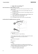
Page 38: ...achine operator For transport reasons the machine base is delivered dismantled 1 Remove the front section and rear wall from the machine 2 Remove the wooden panel from inside the machine 3 Remove the side section from the pallet 4 Remove all pallet brackets Place the machine on its side and mount the base WARNING Tipping over of the machine Serious injury due to the high machine weight Consider th...

Page 39: ...nal assistants The machine base is to be screwed on to the underside of the machine chassis 1 Place two beams and a panel or a second pallet behind the machine 2 Push the clamping lever inwards and lock Both planing tables must be shut completely 3 Several people should be used to carefully place the machine on its back Screw the machine base together and assemble 4 1 2 3 5 Fig 21 Mount the base 1...

Page 40: ...x 4 Tighten all of the screw connections tightly 5 Several people should be used to carefully lift the machine backup Level the machine at the installation location using a spirit level 1 2 Fig 22 Levelling the machine 1 Spirit level 2 Chocks not included in the scope of delivery The floor space around the machine must be flat well maintained free of obsta cles and cleared of waste material such a...

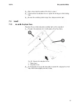
Page 41: ...er from all open machine parts 7 3 Install 7 3 1 Assemble the planer fence The planer fence is delivered partly assembled and must be completed 1 Thread in the adjustment struts into the planer fence from below 1 2 Fig 23 Thread in the adjustment struts 1 Planer fence 2 Adjustment struts 2 Fix the adjustment struts to the fence plate Assemble the components so that they can be moved slightly but h...

Page 42: ...4 1 Fig 24 Fix the adjustment struts 1 Fence plate 2 Flat head screw 3 Plastic washers 4 Cap nut 3 Mount the clamping screws 1 2 3 4 Fig 25 Mount the clamping screws 1 Carriage bolt 2 Plastic washers 3 Indicator plate 4 Clamping screw ...

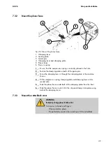
Page 43: ...ns 3 Screw the clamping lever in through the clamping plate in the machine chassis 4 Fit the compression spring clamping plate and clamping lever on the second side 5 Slide the planer fence under both of the clamping plates from the front 6 Slide the planer fence in until it hits the stop and clamp it into place using both of the clamping levers 7 3 3 Mount the cutterblock cover WARNING Extremely ...

Page 44: ...idge guard arm 4 Clamping screw 5 Protective guard Tool Hex key 1 Loosen the clamping screw 2 Slide the protective guard into the arm of the bridge guard 3 Tighten the clamping screw 7 3 4 Mount the handwheel 1 2 3 Fig 28 Mount the thicknesser handwheel 1 Handwheel 2 Carriage bolt 3 Nut and washer Tool Spanner 10 mm 1 Insert the carriage bolt through the arbour ...

Page 45: ...action performance must be sufficient to achieve the negative pres sure and air speed required at the connection point see technical data or layout Check extraction power before initial start up and after significant changes to the machine and or extraction system Before the machine is put into operation for the first time the dust extraction setup must be checked Check for obvious defects on a da...

Page 46: ... WARNING Electric current Serious injury or death Changes to the connection cable can only be carried out by a trained electrician Checking the loop impedance and the suitability of the over current protective device must take place at the location where the machine is to be commissioned by a qualified electrician The machine is equipped with a plug with an earth contact If required the customer m...

Page 47: ...nd feed speed Type and number of planer knives 1 2 Fig 30 Adjust the depth of cut 1 Set the depth of cut infeed planing table 2 Depth of cut scale The depth of cut is adjusted with the adjustment wheel on the infeed side of the planer table Turn the wheel until the desired value is displayed on the scale 8 1 2 Adjusting the joint In particular cases extremely conical or concave or straight joints ...

Page 48: ...ng must be checked with a gauge Chapter 8 1 4 Check the setting of the planer table on the outfeed side on page 49 1 2 A B Fig 32 Adjusting the height of the outfeed side of the planer table 1 Locking nut 2 Adjust height infeed planing table A Planing table upwards adjustment B Planing table downwards adjustment Tool Combination wrench set 1 Switch off the machine and secure it against being switc...

Page 49: ...itch off the machine and secure it against being switched on again 2 Slide the planer fence all the way to the back move the protective guard all the way to the front 3 Prepare the gauge as shown in the illustration 4 Check of the settings at the front outfeed planer table edge front side protective guard Set the gauge to 0 on the front outfeed side planer table edge 5 Turn the cutterblock manuall...

Page 50: ...ing horizontal adjustment 2 Clamping angle adjustment 3 Scale angle adjustment 4 Read angle adjustment Tilt planer fence 90 45 1 Switch off the machine 2 Open angle adjustment clamp 3 Set the required angle tilt the fence plate using both hands 4 Read the angle from the scale 5 Lock the clamp Slide the planer fence forwards or backwards 1 Switch off the machine 2 Open the clamp for the horizontal ...

Page 51: ...ch off the machine and secure it against being switched on again 2 Release the planer guard clamp 3 Turn the bridge guard by 180 and clamp again 4 Release the planer fence clamp 5 Pull the planer fence all the way to the front and remove it 6 Remove the extraction hose from the extraction hood 1 2 3 4 5 Fig 36 Open planer table 1 Planer table clamping lever infeed side 2 Safety catch infeed side 3...

Page 52: ...he extraction supports 8 2 Changing over from the thicknesser to the planer 1 2 3 5 4 Fig 37 Preparing to changeover 1 Extraction pipe 2 Thicknesser opening height mind 150 mm 3 Swing the extraction hood downwards 4 Safety catch outfeed side 5 Safety catch infeed side Preparing the machine to changeover 1 Switch off the machine and secure it against being switched on again 2 Remove the extraction ...

Page 53: ...and clamp it into place using both of the clamping levers 7 Release the planer guard clamp 8 Turn the bridge guard by 180 and clamp again 9 Connect the extraction hood to the extraction supports 8 3 Adjust the thicknesser unit 8 3 1 Thicknesser clearance height general information NOTICE Damage due to restriction of the movement direction Danger of wedging when moving the thicknesser downwards Ens...

Page 54: ...play 2 Thickness planing height scale Depending on the configuration the specified value can be read on the scale accurate to 1 0 mm or on the digital clock or digital display accurate to 0 1 mm 8 3 2 Thicknessing bed adjustment with handwheel 1 3 2 Fig 40 Adjust the thicknessing height 1 Height adjustment handwheel thickness planing height 2 Scale Thicknessing passage information 3 Clamping lever...

Page 55: ...s 1 Switch off the machine 2 Loosen the clamping lever 3 Measure the thickness of the workpiece 4 Use the system handwheel to set the desired dimension Depth of cut Thickness of the workpiece minus the value set 5 Clamp the clamping lever ...

Page 56: ...on before turning on the machine NOTICE Operating Room temperature Damages due to storage material damage The machine may only be operated in dry and frost free rooms at temperatures between 10 and 40 C 1 2 Fig 41 Switching on and off 1 Green start button 2 Red stop button switch machine off Switching on 1 Connect the machine to the main power supply 2 Switch on the cutterblock and feed with the g...

Page 57: ... 2 1 Working positions Planing WARNING Ejected workpieces workpiece parts Severe injuries and damage to property Assume the correct working position Never stand directly within the line of sight of the machining units when the machine is switched on regardless of whether the machine is working or idling Only process the workpiece by feeding in against the direction of rotation 1 2 Fig 42 Working p...

Page 58: ...e parts Splintering workpieces when working at a larger depth of cut 4mm When processing workpieces that are thinner than 10 mm only set a small depth of cut max 10 of the workpiece thickness The finished planed workpiece must not be thinner than 6 mm When using appropriate auxiliary equipment and observing the safety distances to the surroundings there are no limits to the workpiece length Length...

Page 59: ...ush stick at the end of the planing process if necessary 7 If you are not going to continue working switch off the machine and secure it against being turned on again 9 3 Processing techniques when planing 9 3 1 Planing Adjust the cutterblock protective guard 1 2 3 Fig 43 Planing protective guard 1 Protective guard 2 Workpiece thickness less than 75 mm 3 Workpiece thickness greater than 75 mm Work...

Page 60: ...back over the protective guard into the starting posi tion 9 3 2 Planing the narrow edge Fig 45 Planing Planing the narrow edge 1 Take note of general procedures for permitted working methods Chapter 9 2 5 Work process with permitted working methods on page 58 2 Place the protective guard on the planer table and cover all the cutterblock with the exception of the width of the workpiece 3 Press the...

Page 61: ...ent preparation Contact with the rotating cutterblock Use a push block and pushing grip Use an auxiliary fence that has a width of at least 60 mm Protective equipment Push stick push grip 1 Take note of general procedures for permitted working methods Chapter 9 2 5 Work process with permitted working methods on page 58 2 Adjust the cutterblock protective guard Chapter 9 3 1 Planing on page 59 3 Pu...

Page 62: ... from slipping from the angled surface press the workpiece predominantly against the fence and only lightly against the planer tables 5 Additional procedures as described in the chapter Planing narrow edges Chapter 9 3 2 Planing the narrow edge on page 60 Bevelling and chamfering of smaller workpieces You must always use a special jig for chamfering or bevelling small narrow workpieces This jig ca...

Page 63: ...ieces Ensure sufficient distance to neighbouring machines to walls or other solid objects 2 1 Fig 49 Working position thickness planing 1 Working position thickness planing 2 Processing direction 9 4 2 Authorised thickness planing working methods During thickness planing workpieces with an already planed surface are planed thinner in parallel Precise parallel thicknesses can only be obtained if th...

Page 64: ...es can only be processed by using extra tools e g pushing stick Length min 145 mm Width max 254 mm Thickness min 5 mm max 184 mm 9 4 5 Thickness planing WARNING Serious hand injuries danger of being pulled in Contact with the rotating cutterblock Assume the correct working position Never reach into the infeed or outfeed whilst the machine is running during the process or running idle NOTICE Large ...

Page 65: ...ink required true 2 Every time the machine is put into operation test the kickback guards to ensure that they are functioning properly 3 Switch on the machine start the drive motor The feed gear runs automatically when the drive motor is switched on 6 Place the surface planed side of the workpiece on the thicknesser table and push into the machine until it is drawn in by the feed rollers 7 Process...

Page 66: ... 2 Support the workpiece 1 The workpiece must be supported when it comes out of the rear of the machine to prevent it from tipping over 2 Remove the workpiece from the machine 3 Adjust the thicknessing height before planing again Pay attention to maximum depth of cut 4 Push the workpiece back into the machine on the infeed side ...

Page 67: ...67 A2 26 Maintenance 10 Maintenance ...

Page 68: ...s equipped with an emergency stop button X 75 10 9 Test the red stop button as the emergency stop if the machine is not equipped with an emergency stop button X 75 10 2 Cleaning and lubricating Do not use compressed air to clean as this will blow dust and shavings into the various ball bearings and guides Only use low dust emission vacuum to remove dust deposits Carry out cleaning when required af...

Page 69: ...es planer fence 4 Guiding surfaces thicknesser table 5 Transport rollers and kickback guards 6 Space under the thicknesser table Protective equipment Protective clothing Protective gloves Safety goggles Tool Cleaning cloths Resin remover Vacuum cleaner 1 Switch off the machine and secure it against being switched on again 2 Clean the machine of dust shavings waste material and other contami nants ...

Page 70: ... Remove the planer fence 4 Remove transport rollers cover pan head screws 5 Drive belt cover nuts The maintenance cover for the transport rollers drive as well a the belt drive can be found at the rear of the machine Tool Allen key 4 mm Ring spanner 10 mm 1 Switch off the machine and secure it against being switched on again Disconnect the machine from the mains power supply 2 Tilt down the bridge...

Page 71: ...ers 2 Kickback guards 3 Planed panel Check kickback guards clean transport rollers Protective equipment Protective clothing Protective gloves Safety goggles Tool Cleaning cloths Resin remover Vacuum cleaner 1 Clean the transport rollers monthly from resin residues 2 Check condition of kickback guards The kickback guards must not show any signs of damage 3 Test the function on a daily basis and rem...

Page 72: ... tension is specified as an oscillation frequency in hertz Hz The correct belt tension can only be checked with a measuring device 1 2 3 4 Fig 55 Checking the drive belt 1 Nuts and washers 2 Cover lid 3 Drive belt tension 74 80 Hz 4 Drive belt Tool Screwdriver with star bit 1 Switch off the machine and secure it against being switched on again 2 Disconnect the machine from the mains power supply 3...

Page 73: ...move the screws and washers 4 Remove lid Chapter 10 4 Preparation Remove the maintenance cover on page 70 5 Clean the drive chain and then reapply machine grease lubrication Slowly turn the chain in a clockwise direction using a socket wrench 6 Repeat the process until the whole chain is lubricated 7 Remount the cover Chapter 10 4 Preparation Remove the maintenance cover on page 70 10 8 Lubricate ...

Page 74: ...upply 4 Loosen and remove the nuts and washers 8x 5 Remove lid Chapter 10 4 Preparation Remove the maintenance cover on page 70 6 Clean the spindles and then reapply machine grease lubrication 7 Move the thicknessing bed all the way down and then all the way back up again Chapter 8 3 1 Thicknesser clearance height general information on page 53 8 Remount the cover Chapter 10 4 Preparation Remove t...

Page 75: ...ne on using the green start button with the emergency stop button locked machine does not start Unlock the Emergency stop button by turning it Repeat with all Emergency Stop buttons on the machine Machine can not be started Press the red Stop button If present Turn the main switch off position O OFF and secure it Contact Felder Group service Test the red stop button as the emergency stop if the ma...

Page 76: ...tops within 10 seconds Checking the time for the machine to come to a stop completed Machine takes more than 10 seconds to stop If present Switch off Main switch position O OFF Disconnect the machine from the mains power supply Contact Felder Group service Check the extraction hood limit switch 1 2 Fig 58 Check the extraction hood limit switch 1 Move the thicknesser table fully upwards 2 Swing up ...

Page 77: ...machine stops immediately Machine will stop immediately Swing the extraction hood downwards Machine does not stop immediately Swing the extraction hood downwards press red Stop button Disconnect the machine from the mains power supply Contact Felder Group service ...

Page 78: ...he malfunction and cause of the malfunction have been professio nally remedied 2 whether all safety equipment has been installed in accordance with regula tions and are technically and functionally in perfect condition 3 whether there are no individuals located within the danger area of the machine 11 3 Faults causes and repairs The following examples highlight possible undesired conditions of the...

Page 79: ...elt tension is too slack Re tensioning the drive belt The drive belt is worn out Replacing the drive belt Cutterblock cannot be brought to a stop within 10 seconds Fault in the electrical system brake Contact Felder Group service Disruptions whilst processing the workpiece Fault description Cause Remedy Poorly planed surface Planer knives are worn out 1 Replace the planer knives 2 Depending on the...

Page 80: ...ent spring pressure on one side of the infeed side feed roller Contact Felder Group service Oblique cut at the end of the workpiece when thickness planing Outfeed roller spring pressure too low on one side Contact Felder Group service 11 4 Correct the planing fence angle An exact angle between the fence guide bar and planing table is very important when planing the narrow edge and chamfering The 0...

Page 81: ...rtz Hz The correct belt tension can only be checked with a measuring device If any rips or tears are discovered during the monthly tests the belt must be changed 1 2 3 4 Fig 60 Adjust the drive belt tension 1 Motor clamping nut 2 Tightening screw 3 Belt tension during operation 74 80 Hz 4 Belt tension during installation 85 90 Hz Re tensioning the drive belt Tool Combination wrench set Hex key 1 S...

Page 82: ...ts 4x 11 6 Reversing replacing the system planer blades WARNING Extremely sharp planer knife cutters Cut injuries to hands and fingers Wear protective gloves Be particularly careful when working with the cutterblock NOTICE Incorrect planing knives Damage to the machine malfunction or poor planing result Only use original Felder Group planer knives Only use machine specific planer knives Execute th...

Page 83: ...m a planer to a thicknesser on page 51 3 Release all the blade holder screws of a blade and remove the blade holder and planer blades Release all the blade holder screws of a blade and remove the blade holder and planer blades Repeat this process with all blades 4 Clean the planer blades blade holders and cutterblock of traces of resin as thoroughly as possible 5 Reverse the planer knife if only o...

Page 84: ...d for use are listed in a separate spare parts catalogue enclosed in the docu mentation package supplied with the machine Spare part order 3 4 1 2 Fig 62 Spare parts Order 1 Model type 2 Machine number 3 Article number 4 Article description The following information is required when ordering spare parts Type description and machine number according to the identification plate Article number articl...

Page 85: ...onal regulations standards and environmental protection norms ENVIRONMENT Disposing of batteries Batteries are subject to special waste treatment regulations and must be disposed of in accordance with locally enforced regula tions The improper handling of batteries can due to their potentially dangerous substances have a negative environmental effect and consequences for human health For this reas...

Page 86: ... 6WHOOULQJ 6FKHLEH 0 HZ 6WLIW 0 6FKHLEH 0 6NW 6FKUDXEH 0 6NDOHQKDOWHU OHLWODJHUIODQVFK QEXVVFKUDXEH 0 HJHOUDG DQGUDGZHOOH 7RUEDQGVFKUDXEH 0 6 HZ 6WLIW 0 6NW 0XWWHU 0 YHU LQNW 6NW 6FKUDXEH 0 DQGUDG 6NW 6FKUDXEH 0 1 HZLQGHIXUFK LQVHQVFKU 0 PLW 7RU 6FKHLEH 0 YHU 6NW 0XWWHU 0 YHU LQNW 8POHJJULII 0 OHPPVSLQGHO OHPPKHEHO PLW QQHQJHZLQGH 0 U LVWDQ URKU 0 6NW 0XWWHU 0 IODFK 6WHOOULQJ 6NW 6FKUDXEH 0 RKOVFK...

Page 87: ...H HWULHEHSODWWH DKQ XQG 5LHPHQUDG DKQ XQG HWWHQUDG HWWHU OLHGHU 1XWPXWWHU 0 6NW 5LSSHQVFKUDXEH 0 VFKZDU 6LFKHUXQJVULQJ 6LFKHUXQJVULQJ XQGVFKUDXEH HWULHEH 6SDQQHUSODWWH HWWHQVSDQQUDG 6LFKHUKHLWVPXWWHU 0 HWWHQVSDQQHUDFKVH 6FKHLEH 0 XJIHGHU H R G HWWHQVSDQQHUDFKVH 6NW 5LSSHQVFKUDXEH 0 VFKZDU 6LHKH 3OD 0RWRU 0RWRUULHPHQVFK 9 6FKHLEH 0 YHU 4 6HQNVFKUDXEH PLW 6 0 HWULHEHULHPHQ HGHUULQJ 6NW XWPXWWHU 0 6F...

Page 88: ...Q PLW RQXV 6FKHLEH 0 HZ 6WLIW 0 VS DJHUEORFN 7 DJHUEORFN XV XJVZDO H LQ XJVZDO H 5LOOHQNXJHOODJHU 1XWPXWWHU ODVWLF 6WRS 0 5 FNVFKODJ 6LFKHUXQJVVW 5 FNVFKODJ 6WHOOULQJ 5 FNVFKODJVLFKHUXQJ HZ 6WLIW 0 LFKWVFKHLEH UXFNIHGHU D R G Q HZ 6WLIW 0 7 DJHU 00 5 6FKHLEH 0 YHU LQNW 9 6FKHLEH 0 YHU 0 UXFNIHGHU D R G Q 6LFKHUKHLWVPXWWHU 0 6NW 5LSSHQVFKUDXEH 0 VFKZDU 6HFKVNDQWULSSHQPXWWHU 0 OLQGHUVFKUDXEH H WU QL...

Page 89: ... HLFKQXQJ 3RV 7HLOHQXPPHU 7HLOHEH HLFKQXQJ XI KUHQGHU 7LVFK OHPPKHEHO 7LVFKYHUELQGXQJVEOHFK HLFK 39 7DXFKNDSSH DOOVSHUUH 2 HZ 6WLIW 0 OLQGHUVFKUDXEH H WU QLHGU RSI 0 4 6NW XWPXWWHU 0 HZ 6WLIW 0 VS UXFNIHGHU D R G Q LQVHQVFKUDXEH PLW 6 0 EGHFNEOHQGH UHFKWV 6FKHLEH 0 YHU LQVHQVFKUDXEH PLW 6 0 1 6LFKHUXQJVULQJ EI KUHQGHU 7LVFK OLQGHUVFKUDXEH H WU QLHGU RSI 0 EGHFNEOHQGH OLQNV ...

Page 90: ...DOWUlJHU 3DUDOHOODQVFKODJ LQHDODXIQDKPHZLQNHO LQHDO OLQGHUVWLIW K 6FKHLEH 0 4 5lQGHOPXWWHU 7 0 LQVHQVFKUDXEH PLW 6 0 QDNWLY 7HOOHUIHGHU 7RUEDQGVFKUDXEH 0 0 HZ 6WLIW 0 PLW XQVWVWRIIVSLW H 6NW 0XWWHU 0 IODFK 6HQNVFKUDXEH PLW 6 0 4 6NW XWPXWWHU 0 6NW 0XWWHU 0 YHU LQNW 6FKLHEHEOHFK QVFKODJEOHFK 6WHOOVWUHEH 3DUDOOHODQVFKODJ QGLNDWRUEOHFK 6NDOD 3DUDOHOODQVFKODJ 7 OHLWIROLH 9LHUNDQWPXWWHU YHU 0 6FKHLEH 0...

Page 91: ...WLVFK QGVFKDOWHUEHWlWLJXQJVERO HQ 6LFKHUKHLWVPXWWHU 0 6LFKHUXQJVULQJ 6LFKHUXQJVVFKHLEH UXFNIHGHU D PP R PP G PP Q XJHOSIDQQH 6HQNVFKUDXEH PLW 6 0 OHPPVWHPSHO RO HQI KUXQJ 6NW 0XWWHU 0 YHU LQNW QGVFKDOWHUEOHFK 6NW 0XWWHU 0 YHU LQNW 4 5DPSD LQVFKODJPXWWHU 0 3 6NW 6FKUDXEH 0 QEXVVFKUDXEH 0 6FKZHUVSDQQVWLIW lFKHUVFKHLEH 0 QEXVVFKUDXEH 0 VLHKH 3OD 5ROOHQHQGVFKDOWHU QEXVVFKUDXEH 0 6NW 0XWWHU 0 YHU LQNW ...

Page 92: ...92 Attachment 12 4 Circuit diagram ...

Page 93: ......

Page 94: ...FELDER KG KR Felder Straße 1 6060 HALL in Tirol AUSTRIA Telephone 43 5223 5850 0 Email info felder group com Internet www felder group com ...

Reviews: