background image


PicoKeyer-Plus 

05/25/2014 (Firmware V4.5) 

Page 13 of 19 

Now find the 8-pin IC socket.  Orient the socket so that the notched 
end is at the end indicated by the silkscreen markings.  Insert the pins 
into the PCB.  You may need to bend the pins at any two diagonally 
opposite corners flat against the bottom of the PCB to hold the 
socket in place while you solder.  Solder all eight pins in place.  Be 
careful not to use too much heat or too much solder. 


Find the speaker and install it in the location marked SPKR.  The 
speaker may be marked with a + on one side; don’t worry about 
polarity as it can be installed either way.  Make sure the speaker is 
inserted fully into the holes before soldering.  Don’t bend the leads 
of the speaker; you may want to use a bit of adhesive tape to hold it 
in place.  Don’t spend too much time soldering the speaker or it may 
be damaged.  


At this point, you have two options for powering your keyer.  The included coin cell battery will power your kit for quite 
a while, usually a couple of years or more under normal use.  In some cases, however, you may wish to use an external 
source of DC power instead.  Examples would be if you plan to build your keyer into a transmitter or transceiver, or for 
use as part of a beacon station that will transmit continuously.  If you choose to use the on-board battery, install the 
battery holder.  For external power, leave the battery holder off and install the resistor and Zener diode instead.  I 
recommend using the battery unless you are building your PicoKeyer-Plus into another piece of equipment such as a 
transmitter or transceiver.  DO NOT use both external power and the battery – ever! 


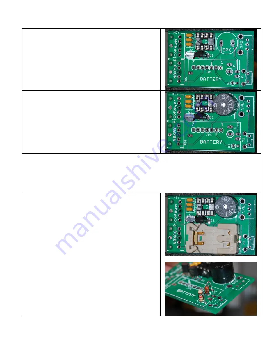
To use the on-board coin cell battery

, locate and install the battery 

holder.  You may need to use a piece of adhesive tape to hold it in 
place while you solder.   


OR — 

If you wish to use external DC


power

, omit the battery holder.  

Install 1K (Brn-Blk-Red) resistor R1 and Zener diode D1 instead.  
The banded end of D1 should be toward the white circle marked on 
the PCB.  (Note: If you have an older circuit board, this resistor may 
be marked R3.  On those older boards, R1 is not used.) 


Summary of Contents for PicoKeyer-Plus

Page 1: ...h manually formed dashes Speed adjustable from 5 to 60 WPM via menu OR speed control potentiometer Speed control can be set to your preferred speed range Dual Set Speed allows quick QRS QRQ and return to favorite speed Adjustable weight Variable pitch audio sidetone Curtis A or B bug and Ultimatic keying modes Variable letter spacing Tune mode with on off carrier or automatic string if dits for ea...

Page 2: ...ur speed set at a constant favorite speed but have the option of rapid QRS QRQ to answer faster or slower stations Or you can simply ignore the stored speed and always use the pot for speed control it s up to you One thing to note you can set the stored speed anywhere from 5 to 63 WPM and it doesn t have to be within your pot speed control range You can also set the range of the speed control to w...

Page 3: ...does not sleep between messages while in beacon mode If you use your PicoKeyer to control a beacon full time you should use an external power source This can be as simple as a pair of series AA or AAA alkaline cells or you can use the kit s Zener diode and resistor for power sources up to about 20 Volts DC Battery replacement is straightforward just remove the two screws from the cabinet bottom op...

Page 4: ...he PicoKeyer with a rig requiring grid block or cathode keying voltages over 60 V you will need to use a separate high voltage keying adapter The Universal Keying Adapter 3 available from NØXAS at www hamgadgets com is optically isolated and will handle solid state grid block or cathode keyed transmitters at up to 400 V Of course you can always build your own Keying Modes What s Mode A Mode B and ...

Page 5: ...eyer need to be connected Doing it wrong could possibly damage your rig and or your keyer However presented here are a few examples that you may find useful for setting up your station for FM code practice Refer to the operator s manual for your rig for specific requirements for PTT and audio Using MCW mode requires making soldered connections to a set of solder pads JP1 which is located underneat...

Page 6: ...eying FM mobile rigs Figure 4 shows the method used with mobile or fixed station rigs You will likely find it easiest to connect the keyer via the packet data connector The schematic shows an optional audio level control potentiometer that may or may not be needed ...

Page 7: ...installed and set for 20 WPM The keyer will announce 20 13 If you have the pot set to its minimum you will be using the stored speed and the keyer will only announce the stored speed since it is the same as the current speed It sounds more complicated than it is play with it a little and you ll get the hang of it You can adjust the stored speed from the menu Tapping the dot paddle will decrease th...

Page 8: ... your message automatically repeat at timed intervals insert the command B BEACON at the end of your message This will cause the keyer to delay for the number of seconds set with the B parameter see below and re send the message You can terminate beacon operation by tapping either paddle or the button This can be especially useful for calling CQ or to use your PicoKeyer to control a propagation be...

Page 9: ...N Note that this only affects the way QSO numbers are sent Other numbers in stored messages or numbers sent by hand are not affected The default setting is no cut numbers Z Default N Leading Zeros The keyer will send Y or N and wait As with other menu settings either paddle may be used to switch between the two settings Y will send numbers in stored messages with up to two leading zeros 1 is sent ...

Page 10: ... Command Mode You can select between Button mode BTN or Paddle mode PDL In Paddle mode you will hear a prompt once you enter setup mode Simply use your paddle to send the Morse letter of the option you want to review or change For example to set the speed you would send S To leave a menu item tap the button to return to the prompt To leave setup mode either tap the button again or send SK with you...

Page 11: ...ar bench vise use gentle pressure and something to cushion the vise jaws A pencil to check off each step as you finish it Once you have all of your tools and supplies gathered together you re ready to get started Warm up the iron while you remove the parts from the bag and lay them out on the work surface We ll start with the small parts and work our way through each component checking them off on...

Page 12: ...e up as you look at it Your board may or may not have the component designators C1 C2 C3 Q1 etc marked Since all of the same type of parts are the same value this shouldn t cause you any problems at all Locate the three ceramic capacitors in your kit These will be small rectangular parts with two parallel leads All three are 01 μF marked 103 Install the three capacitors in the locations shown for ...

Page 13: ...ower your kit for quite a while usually a couple of years or more under normal use In some cases however you may wish to use an external source of DC power instead Examples would be if you plan to build your keyer into a transmitter or transceiver or for use as part of a beacon station that will transmit continuously If you choose to use the on board battery install the battery holder For external...

Page 14: ...in to get them fully seated There are three plastic bumps on the bottom that will fit into holes in the PCB when they are pushed all the way in Install the two threaded knurled collars on the two stereo jacks This keeps them from getting lost You can use them to mount your PicoKeyer in a box or tin We re almost there Find the PicoKeyer chip and remove it from its protective anti static package foa...

Page 15: ...ign This side will be up when the battery is inserted into the battery holder Insert the battery into the battery holder If you have done everything right you should hear the keyer send 73 in Morse code through the speaker Congratulations Your kit is complete If you have the optional cabinet now would be a good time to mount your keyer in the cabinet Make sure the speaker is underneath the holes d...

Page 16: ...el or similar tool If you have an older board that doesn t have those pads locate the PCB trace from the speaker to pin 2 of the PIC chip and cut it You can then tack solder the wires to the headphone jack to the two end points pin 2 of the chip and the non grounded speaker pin Cut the PCB trace indicated by the arrow in the diagram on the left The switched wire from the headphone jack the center ...

Page 17: ...harge including postage I m pretty easy to get along with Q The sidetone audio is too low I can t hear it A You can adjust the sidetone audio frequency menu setting A it will get quite a bit louder near the speaker s resonant frequency around 2 kHz If that doesn t do enough for you you may want to use a small audio amplifier and larger speaker You might try covering the small hole in the top of th...

Page 18: ... during power on You need to remove the battery plug in the straight key then insert the battery It s a good idea to press the setup button for a second or two while the battery is out to make sure the chip gets completely reset Q When I plug the keyer into my radio I get constant dashes or dots and weird results when I try to use the paddle A Make sure your rig s internal keyer is turned off and ...

Page 19: ... Sidetone S Speed K Keying Mode A B Umatic buG Straight M Memory P Paddle reverse Q QSO Set A Audio tone RL Speed pot Range Lo D Xmit precomp Delay RH Speed pot Range Hi V Firmware Version L Letter spacing 0 9 C Command mode X Cut numbers 0 9 F Factory Reset Header JP1 Connections JP1 1 Ground JP1 2 DC power 3 14V DC Only JP1 3 Sidetone Audio JP1 4 Pushbutton Switch JP1 5 Keying 60V 200 mA Max JP1...

Reviews: