25
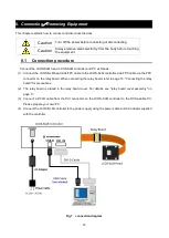
2. Configure your PC.
See "How to set DVI video output" on page 21.
3. Turn on the LCOS-SLM.
Warm up for about 10 minutes.
4. A computer hologram is input.
Display the attached file sample _ hologram _ hpk _ xxx _ yyynm.bmp (xxx is the LCOS-SLM head S/N,
and yyy is the wavelength.) on the 2nd screen. This pattern is a computer generated hologram (CGH)
pattern that forms the letters "HPK" on the Fourier plane. The initial shape distortion correction pattern of
the LCOS-SLM head is added.
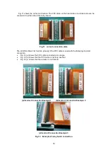
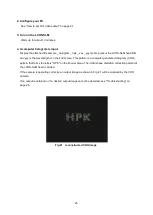
If the camera is operating correctly, an output image as shown in Fig. 21 will be captured by the CCD
camera.
If no output is obtained or if a desired output image cannot be obtained, see "Troubleshooting" on
page.26.
Fig.21
reconstructed CGH image


