background image


10

7. 

Names and descriptions of parts


This section describes the names and descriptions of each part of the device and the bundled product. 
 

7.1 


LCOS-SLM Head 

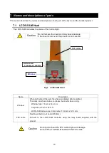
The LCOS-SLM modulates the phase of the incident light. 


Caution


Do not remove the cover as it may cause damage. 
If the cover is removed, the product is not covered.


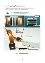
Fig.4    LCOS-SLM Head


Name 

Description 

Window 

When light enters this part, the phase-modulated light is emitted. 
The sizes are shown below, so please be careful when using. 

Window Size: 18 mm x 14.4 mm 

Chip Size: 22 mm x 22 mm 

LCOS-SLM Active area: Chip Center 15.9 mm x 12.8 mm 

FPC cable 

Flexible printed circuit board (450mm).   

Connect  to  the  LCOS-SLM  controller  using  the  relay  board  supplied  with  the 

product. 


Caution


Do not pull or bend the FPC cable to prevent damage. 
Do not lift the LCOS-SLM head with the FPC cable.


Liquid crystal molecule   

orientation direction 


Window 

FPC cable 

Active area:   

15.9 mm x 12.8 mm 

Summary of Contents for LCOS-SLM X15213 Series

Page 1: ...ad this operation manual carefully before using this device Failure to follow the instructions in this manual may result in a serious accident Keep this manual in a convenient location at all times Do...

Page 2: ...perty Our company is not responsible for such use Unpack the device and check the contents If the equipment is damaged or there is a shortage of accessories contact our company without operating the p...

Page 3: ...pany assumes no responsibility or warranty for any damage caused by using the FOMA terminal in contravention of these precautions The following symbols are used in this manual DANGER Indicates an immi...

Page 4: ...ness Take appropriate measures such as using a beam damper to block light or wearing protective glasses to prevent light from entering the eyes Watch out for the diffracted light LCOS SLM generates un...

Page 5: ...after referred to as PC etc Set the display properties as follows Type X15213 Series Screen size 1280 1024 SXGA Refresh Rate 60 Hz Colors True Color 32 Bit About warm up operation After the power is t...

Page 6: ...rd cover 12 7 4 Power Cable AC Adapter 13 7 5 DVD contains distortion correction pattern and control software 13 8 Connecting Removing Equipment 14 8 1 Connection procedure 14 8 2 Connecting the relay...

Page 7: ...amount changes according to the input gradation value The LCOS SLM s non linear response and phase modulation characteristics which vary from device to device are corrected by adjusting parameters at...

Page 8: ...itions Parameter Value Unit Place of use indoor use Operating altitude 2000 m Degree of pollution 2 IP code IP 20 IK code IK08 Recommended Operating Environment Temperature 25 C Operating humidity 30...

Page 9: ...oltage Output 24 V Output voltage fluctuation Output 5 Ripple Output 0 24 MAX V Output current Output 2 71 MAX A Over Voltage Protection Output 36 MAX V Plug shape Output 5 5 2 1 L 9 5 mm Note1 Do not...

Page 10: ...liquid crystals generally respond non linearly to input voltages linear phase modulation is achieved with respect to input values by incorporating a look up table LUT Look Up Table within the drive ci...

Page 11: ...w When light enters this part the phase modulated light is emitted The sizes are shown below so please be careful when using Window Size 18 mm x 14 4 mm Chip Size 22 mm x 22 mm LCOS SLM Active area Ch...

Page 12: ...to the LCOS SLM controller using a DVI D cable to control the output pattern of the LCOS SLM head This document focuses on DVI control USB B connector Connect your PC to the LCOS SLM controller using...

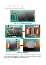
Page 13: ...d to the LCOS SLM controller See Connecting Removing Equipment on page 14 for connecting Caution Be sure to attach a cover to the relay board Peripheral devices may be affected Fig 6 Connecting the re...

Page 14: ...have an initial geometric distortion that is unavoidable in manufacturing For details see Distortion correction pattern on page 28 The DVD contains a pattern to compensate for this distortion The dis...

Page 15: ...e FPC cable to the LCOS SLM controller side FPC cable via the FPC connector on the relay board When connecting the relay board refer to page 15 Connecting the relay board for precautions 2 The relay b...

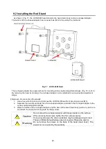
Page 16: ...ng do not use any tools and use your fingertips to lift up the center part Fig 8 Precautions when tilting the actuator Fig 9 Precautions for raising the actuator 2 FPC Cable Connection Guidelines Be c...

Page 17: ...will not function properly if the FPC cable is used with the following incorrect connection Fig 12 a shows the FPC cable connected at an angle Fig 12 b shows that the FPC cable is not fully inserted F...

Page 18: ...shown in Fig 14 insert the FPC cable vertically so that the GND contact of the FPC cable contacts the gasket of the relay plate cover Assemble the cover plate so that the mounting projections enter e...

Page 19: ...ch 2 Remove the relay board cover screws and remove the cover 3 You can remove various cables Caution The head and the FPC cable connected to the controller cannot be removed If you try to remove it f...

Page 20: ...ase of the oblique incidence optical system of Example 2 the incident light should be incident with horizontal polarization Note Note Horizontal polarization is the direction of polarization parallel...

Page 21: ...ve the LCOS SLM head front securing screws M3 2 Separate the head main body from the L shaped adapter and attach the L shaped adapter to the various optical adjustment stages 3 Wipe the surface of the...

Page 22: ...s the orientation direction of the liquid crystal only the phase of the incident light can be modulated Fig 19 liquid crystal orientation direction Advice Be sure to use horizontally polarized light N...

Page 23: ...top example Here is an example of PC configuration Have a desktop PC with 2 port DVI output The first output signal is connected to the monitor of the PC The second output signal is connected to the L...

Page 24: ...e included with the product 3 Creating a Phase Image For how to create the phase image refer to the LCOS SLM phase control method section in the software operation manual 4 Distortion correction patte...

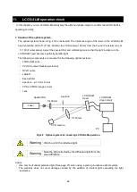
Page 25: ...parallel light The following components are required for the following optical systems LCOS SLM suite PC DVI output Desktop preferred DVI D cable LASER Special filter Aperture 12 mm or less CCD or CMO...

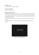
Page 26: ...he wavelength on the 2nd screen This pattern is a computer generated hologram CGH pattern that forms the letters HPK on the Fourier plane The initial shape distortion correction pattern of the LCOS SL...

Page 27: ...by the controller If so try 1 to 5 below 1 Make sure the DVI D cable is connected properly The cable may not be connected properly Turn off the power to the controller and reconnect it 2 Disconnect a...

Page 28: ...ipment The desired diffraction pattern cannot be obtained Check the polarization direction of the incident light In the case of light perpendicular to the alignment direction of the liquid crystal or...

Page 29: ...is the mirror surface causes wavefront distortion as shown in Fig 22 Fig 22 Deformation of the output wavefront due to LCOS SLM distortion The distortion correction pattern corrects wavefront distorti...

Page 30: ...n and violation of various conditions concerning the environment application field usage storage disposal etc described in this document even within the warranty period The application of this materia...

Page 31: ...30 15 Dimensional outline Unit mm Unindicated tolerance 1 0 LCOS SLM Head...

Page 32: ...31 Unit mm Unindicated tolerance 1 0 LCOS SLM Controller...

Page 33: ...inside Recommended Usage Conditions Parameter Recommend condition Circulating water temperature 25 C Circulating water quality Soft water except for deionized water Circulating water flow 0 5 L min o...

Page 34: ...ulating water temperature at 25 C or simply an air cooled circulating water controller such as a CPU cooler can be used in an environment where the room temperature is 25 C Condensation When circulati...

Page 35: ...hose For example TU0604 series is recommended Installing a water circulation hose Check that the circulating water controller is stopped and that the power of the LCOS SLM is OFF Places the LCOS SLM h...

Page 36: ...l water stops coming out Places the LCOS SLM head in a stable plane Remove the hoses from the LCOS SLM head one at a time to wipe off the water Take care not to splash water and pull out the hose whil...

Page 37: ...th a dry cloth etc and attach the L shaped adapter with the fixing screws Caution Do not screw the L shaped adapter with foreign matter on the surface When securing the screws tighten the four screws...

Page 38: ...37 17 External Dimensions water cooled type Unit mm Unindicated tolerance 1 0 LCOS SLM Head R Series LCOS SLM Head L Series 1 KQB2S06 01S SMC Compatible Tube Outer Diameter 6...

Page 39: ...otonics K K Laser Promotion Division 1 8 3 shinmiyakoda kita ku Hamamatsu City 431 2103 Japan Telephone 81 53 484 1300 Fax 81 53 484 1317 U S A Hamamatsu Corporation 360 Foothill Road Bridgewater N J...

Reviews: