Supplied By www.heating spares.co Tel. 0161 620 6677
PARTS REPLACEMENT
9
9.1
HEAT EXCHANGER
9.2
COMBUSTION CHAMBER INSULATION
9.3
FAN ASSEMBLY
9.4
BURNER
9.5
IGNITION & DETECTION ELECTRODES
9.6
MULTIFUNCTIONAL GAS CONTROL
a)
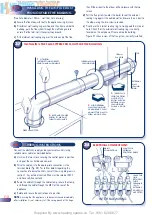
Remove both casing front panels as follows: Pivot the lower
front panel downwards and pull forwards to release. Unscrew
the upper panel retaining screw and lift off the upper casing
panel.
b)
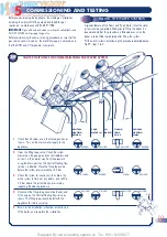
Remove the sealed chamber front panel (4 screws).
c)
Remove the nut securing the burner to the burner locating
bracket (and burner earth wire).
d)
Remove the combustion chamber front panel and burner
locating bracket (7 screws). Take care not to damage the
insulation.
e)
Unscrew and remove the two screws securing the control
panel in the upright position and pivot the control panel
forwards.
f)
Remove the plug from the side of the control panel and unclip
the grommet in the bulkhead below the burner to release the
earth, ignition, and detection wires.
g)
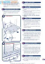
Remove the burner by sliding it forwards with reference to
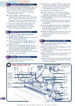
Figure 34.
h)
Turn the CH flow and return valves to the closed position to
isolate the boiler. (see section 5.1), then drain the appliance
using the drain cock provided on the CH flow valve.
i)
Carefully remove the LH combustion chamber insulation panel
to reveal an access hole to the heat exchanger union
connections.
j)
Using a suitable spanner, unscrew the heat exchanger
connections from inside the combustion chamber.
k)
Lift the heat exchanger clear of the two pipes, then remove the
heat exchanger by sliding it forwards.
l)
Replace the heat exchanger and re-assemble in reverse order.
Ensure that all joints and seals are correctly re-fitted and re-
commission the system using the procedure in section 5.1.
a)
Remove the burner as described in section 9.1 steps (a) to (g).
b)
Transfer the ignition and detection electrodes to the new
burner and check that their alignment is as detailed in
figure 35.
c)
Replace the burner (with reference to figure 34) and
re-assemble in reverse order. Ensure that all joints and seals
are correctly re-fitted. (Polarity is immaterial on the fan L and
N connections.)
a)
Remove the burner as described in section 9.1 steps (a) to (g).
b)
Replace the ignition and /or detection electrode(s) and check
that both electrodes are aligned as detailed in figure 35.
Re-assemble in reverse order. Ensure that all joints and seals
are correctly re-fitted.
a)
Remove the casing panels and lower the control box as
described in section 9.1 step (a).
b)
Carefully pull off the electrical connector plug and the two modureg
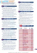
connections from the multifunctional gas control (Fig. 36).
c)
Check that the gas service cock is turned off, and unscrew the
union on the gas cock followed by the four screws securing
the outlet flange and remove the gas control.
d)
Remove the four screws securing the inlet flange to the gas
control, then replace the multifunctional gas control and
re-assemble in reverse order ensuring that the ‘O’ rings are
correctly fitted.
e)
Connect a suitable manometer to the inlet and burner
pressure test points, turn on the gas supply. Check for gas
soundness taking the precautions described in section 5 and
re-commission the appliance in accordance with section 5.3.
In addition it will be necessary to set the DHW heat inputs as
described below:
f)
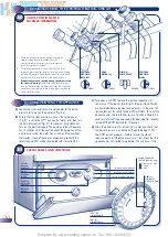
SET THE DHW INPUT AS FOLLOWS: (Refer to figure 36)
1)
Remove the sealing cap of the modureg unit (single fixing
screw).
2)
Isolate the mains electricity supply and disconnect the two low
voltage modulation leads. Restore the mains supply and fully
open any DHW tap. The appliance will light at minimum input.
The design of the appliance is such that the combustion chamber
insulation should not require replacement unless mechanically
damaged. It is recommended that the insulation is dampened
prior to removal to prevent dust.
a)
To replace the combustion chamber insulation front panel
remove the front panel as described in section 9.1 steps (a) to
(c) and replace the insulation.
b)
To replace the combustion chamber insulation side and rear
panels remove the heat exchanger as described in section 9.1
and replace the insulation.
c)
Re-assemble in reverse order. Ensure that all joints and seals
are correctly re-fitted and re-commission the system (if
necessary) using the procedure in section 5.1.
a)
Gain access to the fan assembly by following section 9.1
steps (a) to (d).
b)
Carefully disconnect the tab connectors on the fan wiring.
c)
Disconnect the air pressure switch sensing pipes from the fan,
noting their position.
d)
Remove the fan assembly by unscrewing the two screws,
lowering the assembly and lifting it forwards.
e)
Replace the fan assembly and re-assemble in reverse order.
Ensure that all joints and seals are correctly re-fitted. (Polarity
is immaterial on the fan L and N connections.)
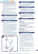
Before commencing any service operation, ISOLATE the mains electrical
supply, and TURN OFF the gas supply at the main service cock.
It is the law that any service work must be carried out by a registered
person.
28
It is recommended that a protective mask is worn when
changing or handling the insulation material.

