Supplied By www.heating spares.co Tel. 0161 620 6677
11
14
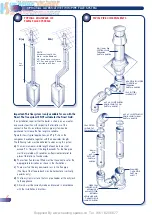
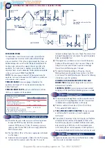
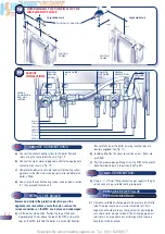
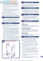
ALTERNATIVE METHODS OF FILLING A SEALED SYSTEM
EXPANSION VESSEL
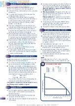
The table below shows the maximum system volume that the
integral expansion vessel can sustain under different charge
pressure conditions. If the system volume exceeds that shown, an
additional expansion vessel must be fitted and connected to the
heating system primary return pipe as close as possible to the
appliance. If an extra vessel is required, ensure that the total
capacity of both vessels is adequate. Further details are available
in the current issues of BS5449 and BS6798.
NOTE
:
If the pressure gauge indicates 2.65 bar or greater when the
appliance is at maximum temperature with all radiators in circulation an
extra expansion vessel is required.
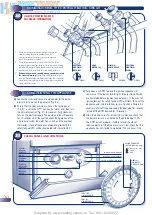
PRESSURE GAUGE
A pressure gauge is situated on the
appliance control panel. This can be viewed by lowering the
bottom front panel.
PRESSURE RELIEF VALVE
A pressure relief valve set at 3 bar
(43.5 psi) is supplied with the appliance.
a)
Check that the mains water pressure is sufficient to produce
the required DHW flow rate, but does not exceed the
maximum DHW pressure (10 bar). If necessary, a pressure
reducing valve must be fitted to the mains supply before the
DHW inlet connection.
b)
The final 600mm (24in) of the mains supply pipe to the boiler
must be copper.
c)
A domestic hot water regulator is fitted within the Finest group
set to control the maximum water flow rate. This may be
removed to obtain higher flow rates. Higher flow rates will not
damage the appliance but may reduce the water temperature
below an acceptable level.
d)
If the appliance is installed in an area where the temporary
hardness of the water supply is high, say over 150ppm, the
fitting of an in-line scale inhibitor may be an advantage.
Consult the Local Water Supplier if in doubt.
e)
For specific information relating to fittings (eg. Showers,
Washing Machines etc) suitable for connection in the DHW
circuit, consult the Local Water Supplier. However the following
information is given for guidance:
DOMESTIC HOT/COLD WATER SUPPLY TAPS AND
MIXING TAPS.
All equipment designed for use at mains
water pressure is suitable.
SHOWERS & BIDETS
. Any mains pressure shower or bidet
complying with the Local Water Undertaking bylaws is suitable.
a)
Wiring external to the appliance must be in accordance with
the current l.E.E. Wiring Regulations (BS 7671) for electrical
installation and any local regulations which apply.
b)
The mains cable must be at least 0.75mm
2
(24/0.2mm)
PVC Insulated to BS6500 table 16.
c) THIS APPLIANCE MUST BE EARTHED.
(Failure to provide
a satisfactory Earth connection will result in appliance
malfunction)
d)
The method of connection to the mains supply must facilitate
complete electrical isolation of the appliance. Either a 3A
Fused three pin plug and unswitched shuttered socket outlet,
both complying with BS1363, or a 3A fused double pole
switch having a 3mm contact separation in both poles and
serving only the boiler (and its external controls) may be used.
The appliance may be used with any Certificated mains voltage
room thermostat as described in section 4.
3.7
DOMESTIC HOT WATER SYSTEM
3.8
ELECTRICITY SUPPLY
3.9
EXTERNAL CONTROLS
EXPANSION VESSEL REQUIREMENTS
Vessel charge and initial
system pressure
Total water content of system
using 7ltr. (1.54gal) capacity expansion
vessel supplied with appliance
For systems having a larger
capacity multiply the total system capacity
in litres (gallons) by the factor to obtain the
total minimum expansion vessel capacity required litres (gallons)
bar
0.5
1.0
1.5
psi
7.3
14.5
21.8
96ltr
73ltr
50ltr
21gal
16gal
11gal
0.0833
0.109 0.156
•
MAINS WATER
SUPPLY
•
•
HOSE
UNIONS
•
DOUBLE
CHECK
VALVE
ASSEMBLY
•
AIR INLET
VALVE
•
STOP
VALVE
•
HEATING SYSTEM
RETURN
•
TEMPORARY
HOSE
•
TEST COCK
•
CISTERN &
OVERFLOW
•
MAINS
WATER SUPPLY
•
PRESSURE PUMP
& REDUCING VALVE
IF REQUIRED
•
STOP
VALVE
•
HEATING
SYSTEM
RETURN
METHOD A
METHOD B
Note:
The appliance has a built in
filling loop


