Supplied By www.heating spares.co Tel. 0161 620 6677
22
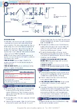
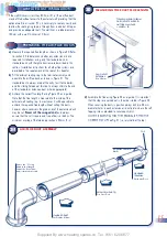
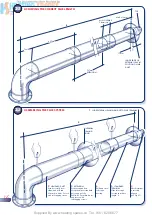
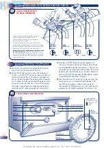
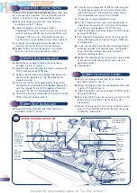
ACHIEVING THE CORRECT FLUE LENGTH
23
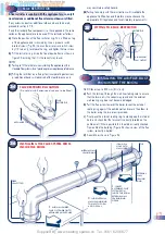
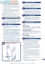
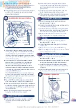
ASSEMBLING THE FLUE SYSTEM
•
•
•
INSIDE EDGE OF
EXTERNAL SEAL IN
POSITION ON AIR
DUCT
•
•
•
•
•
•
•
•
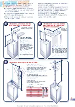
767mm
EXTENSION
MIN. OVERLAP
50mm (2in)
425mm
L
76mm
MAX. 319mm
•
TOP
•
•
•
•
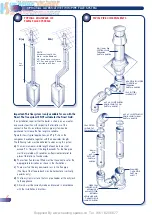
1
SLIDE EXTERNAL SEALING RING UPTO FLUE TERMINAL
L
2
STANDARD DUCT
Push ducts fully over
elbow and drill two
3·3mm dia. holes. Secure
with self tapping screws
•
•
•
•
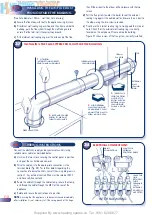
3
EXTENSION
Push extension duct
(if required) over standard
duct, engage fully.
Drill two 3·3mm dia. holes
and secure with
self-tapping screws
6
Drill and screw
telescopic
overlap
5
STANDARD
TERMINAL
Slide telescopic
section to achieve
length ‘L’
4
Check terminal
is correctly
aligned
(see Fig. 27)
•
INTERNAL
SEALING
RING
• •
17mm
16

